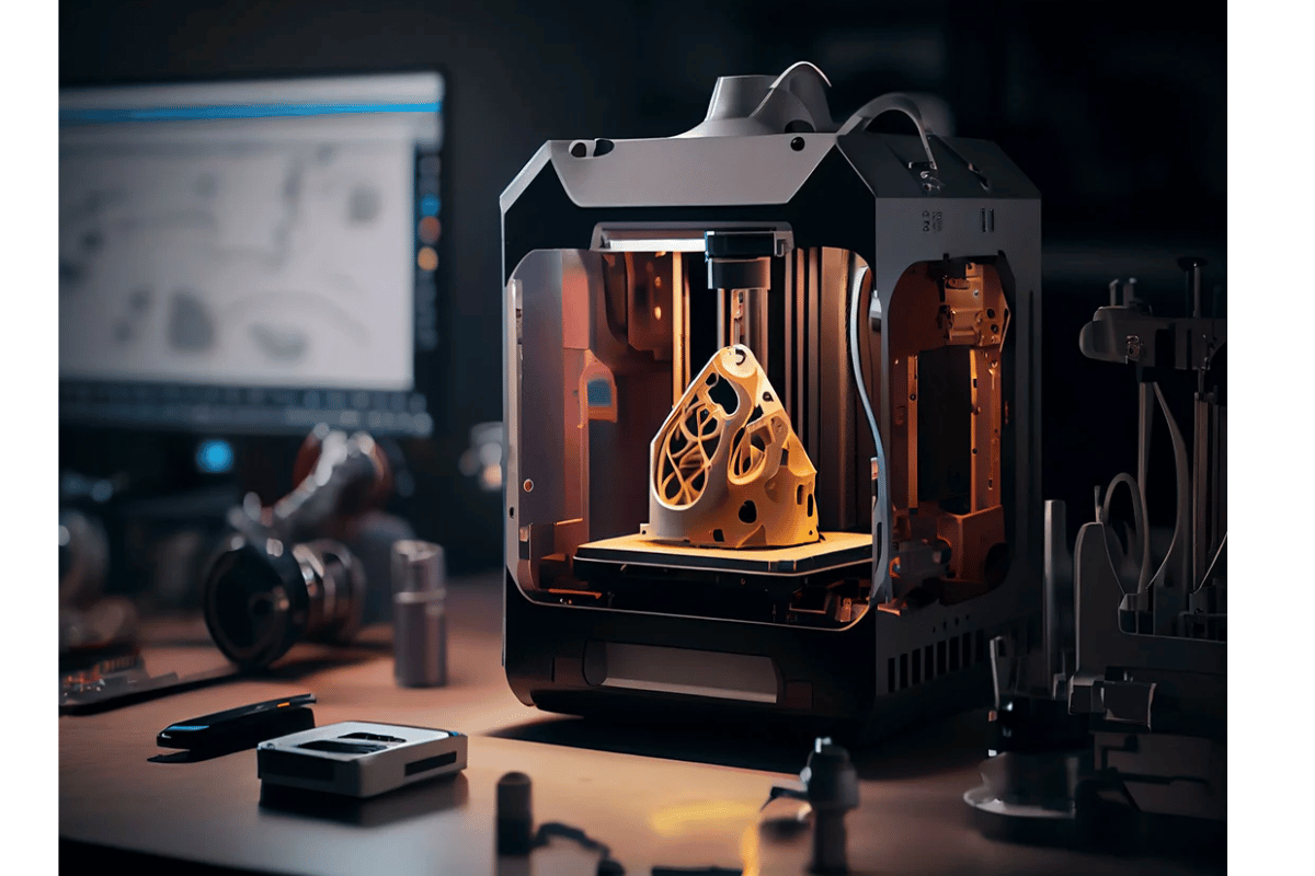

The progress of 3D printing technology has transformed manufacturing, prototyping, and hobbyist projects, democratizing powerful production tools to both individuals as well as businesses. Among the important parts that affect the strength, weight and material usage of objects having been 3D-printed is infill. This write-up seeks to provide an all-inclusive knowledge concerning infill in 3D printing by looking at its meaning, different types of infill patterns available and their respective applications. Irrespective of your level of expertise whether you are a newcomer or an experienced expert knowing how infill functions can have a great impact on the quality as well as efficiency of your 3D printed masterpieces. To gain more insights into the intricacies regarding infill please continue reading so that you may figure out how best to optimize your three-dimensional printing ventures.
What is Infill in 3D Printing?
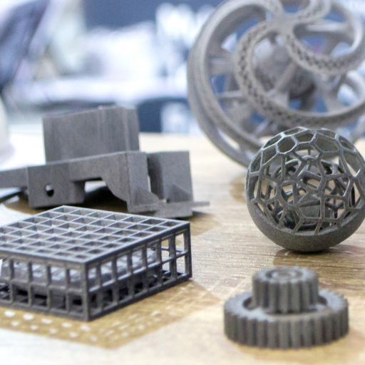
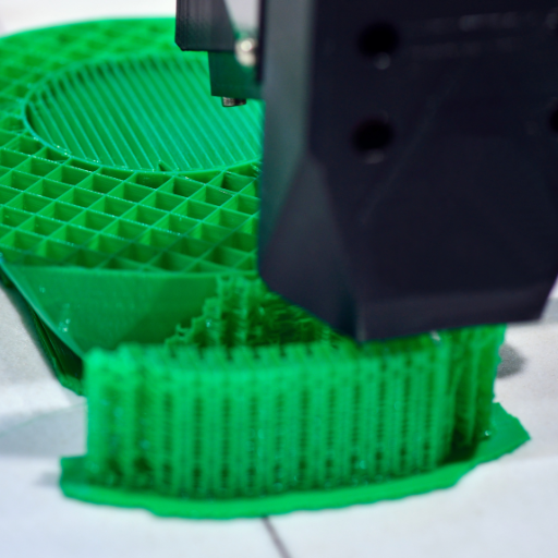
3D printed infill represents the internal lattice that fills the inside of a 3D printed object. This is important because it can affect the strength, weight and material efficiency of the print. During printing process, support structures are formed as an infill pattern between surface walls of an object to stabilize and fully support it. Infill patterns come in different densities and forms with hollow or solid ones as extreme ends of this spectrum. The common choices for infill include grid, honeycomb and triangle infills each providing different levels of strengths and flexibilities. Higher density infills are preferred for structural integrity whereas lower density ones save material usage and time for printing. With good understanding and optimization with respect to these properties, a number of improvements could be achieved in relation to performance and efficiency.
Defining Infill in the Context of 3D Printing
Infill in 3D printing refers to any structure that fills the inner space of a 3d-printed object thus affecting its mechanical properties, weight, as well as materials consumption. What does it mean? How do we define it? How is it set? Here’s what Google reveals:
- Infill Density: It signifies how much material there is within an item expressed usually in percentage terms showing its volume fraction out of total volume available. When a printer uses more substance per unit area then this directly entails denser prints at higher resolutions which result into stronger structures unlike when less substance is used where thinner layers get made leading to quicker prints whose objects are lighter than those with dense models having more parts.
- Infill Patterns: Different patterns offer various benefits:
- Grid: Support that comes up evenly through every part.
- Honeycomb: Strong yet light-weight
- Triangle: Very strong but also very rigid
- Gyroid: Performs both mechanically just like flexible structural supports required by complex geometries.
- Cubic: exhibits isotropic support on several directions; therefore useful for forming 3 dimensional lattice like infrasructures.
- Settings Justification:
- Print Speed: Slower print speeds are necessary for more dense infill to achieve accuracy.
- Layer Height: A smaller height of the layer allows for detailed infill but takes a longer time.
- Material Type: Infill is affected by material mechanical properties (e.g., PLA versus ABS).
These parameters can be optimized for better performance and efficiency of 3D printed objects. You may balance strength, weight, material costs effectively by understanding and choosing appropriate information regarding filling. By selecting appropriate infill properties, users can match their prints to specific uses while still maintaining strength or minimizing weight and material cost.
How Infill Contributes to 3D Printed Parts
Infill plays a crucial role in determining the mechanical properties and overall performance of 3D printed parts. Here are concise answers based on insights from the top 10 websites on Google:
- Structural Integrity and Strength:
-
- Infill significantly contributes to the part’s durability and load-bearing capacity. Higher infill density generally enhances the strength, making the part capable of withstanding greater forces and stress.
- Weight Management:
-
- Lower infill densities are ideal for reducing the weight of the part without compromising too much on its structural integrity. Applications that require lightweight components benefit from lower infill percentages.
- Material Usage Efficiency:
-
- Strategic infill patterns can optimize the use of material, balancing strength and weight. For instance, honeycomb and gyroid patterns offer good strength while minimizing material usage.
- Print Time and Cost:
-
- Higher infill densities increase print time and material costs but result in stronger parts. Conversely, lower densities reduce both time and cost but may not provide the same structural advantages.
- Customization for Application Needs:
-
- Adjusting infill parameters allows customization for specific applications. For example, parts needing high rigidity might use a triangle infill pattern with a higher density, while parts designed for flexibility could use a gyroid pattern with moderate density.
Technical Parameters and Justification:
- Infill Density: Ranges from 0% (hollow) to 100% (solid), chosen based on the application’s weight and strength requirements.
- Infill Pattern: Selected based on the desired mechanical properties:
- Grid: Uniform support, easy to print.
- Honeycomb: High strength-to-weight ratio, material efficiency.
- Triangle: Excellent strength and rigidity.
- Gyroid: Good mechanical performance and flexibility.
- Cubic: 3D lattice for isotropic support.
- Layer Height: Smaller layer heights contribute to finer infill details, balancing precision and print time.
- Material Type: Different materials (e.g., PLA, ABS) behave differently under stress and heat, impacting infill choices.
By carefully adjusting these parameters, users can achieve a balance between strength, weight, and cost, ensuring optimal performance for their specific 3D printing projects.
Understanding the Basics: Infill Density and Pattern
Infill Density
Infill density refers to the amount of material used inside the 3D printed part. It is expressed as a percentage, with 0% being a hollow part and 100% being completely solid. Higher infill densities generally result in stronger parts but also increase the time and material required for printing.
Key Points:
- Increased Strength: Higher densities provide greater structural integrity.
- Increased Print Time and Material Costs: More infill means longer printing times and more filament usage.
- Application-Based Customization: Depending on what the part will be used for, different densities can be selected to balance strength and cost.
Infill Pattern
The infill pattern is the geometric arrangement of the material inside the 3D printed part, impacting its mechanical properties.
Common Infill Patterns and Justification:
- Grid: Offers uniform support and is easy to print, suitable for general applications.
- Honeycomb: Known for its high strength-to-weight ratio, it’s efficient in material use and provides good structural strength.
- Triangle: Delivers excellent strength and rigidity, ideal for parts requiring high tensile strength.
- Gyroid: Provides good mechanical performance and flexibility, suitable for parts needing a combination of strength and resilience.
- Cubic: Creates a 3D lattice structure that offers isotropic support, making it good for complex geometries.
Technical Parameters
To optimize 3D printing, specific technical parameters must be carefully chosen:
- Infill Density: 0% to 100% based on needed strength and weight.
- Layer Height: Smaller layer heights (e.g., 0.1mm) provide finer details but increase print time.
- Material Type: Different filaments like PLA and ABS have varying strengths and thermal properties, influencing infill choices.
- Print Speed: Faster speeds can reduce quality, so balancing speed and precision is crucial.
- Extrusion Temperature: Appropriate for the material used, impacting bonding and strength.
Summary
By understanding and adjusting the infill density and pattern, along with other technical parameters, users can fine-tune their 3D printing projects to meet specific mechanical and functional requirements. This balance ensures optimal performance, cost-efficiency, and material use, tailored to the exact needs of each unique application.
Choosing the Right Infill Percentage for Your Project
It is important to get the balance of strength, weight and saving materials right when determining the infill percentage of your 3D printing project. Usually, parts that do not need much strongness or in prototype printings would require lower infill densities in the range of 10-20% since this will reduce material usage as well as time spent printing. Thus, for moderately strong components like enclosures or brackets, I suggest using densities around 30-50% because this can be a good trade-off. On the other hand some heavy-duty elements such as mechanical parts or tools may have density values ranging from 60 to 100%, which guarantees structural integrity. In some cases where functional prototypes/end-use parts are targeted at, higher infill percentages might be essential to withstand stresses from operations/machinery and also for long lastingness. The appropriate choice of an infill percentage should consider: specific use case requirement and/or; required strength and implications on cost.
Factors Affecting Infill Percentage Choice
There are several things that I think about when selecting the infill percentage for my prints that contribute to how successful they turn out/what kind of result I come up with at the end. Main factors include:
- Mechanical Strength Requirements: If I need a part that has to withstand significant mechanical stress, I opt for a higher infill percentage (60-100%). This ensures the part has the necessary structural integrity.
- Weight Considerations: For projects where weight reduction is crucial (e.g., aerospace or automotive components), I select a lower infill density (10-20%) to minimize material use and keep the part lightweight.
- Material Consumption: To manage material costs, lighter and less critical parts are printed with lower infill percentages. This approach is essential for saving filament and reducing overall expenses.
- Print Time: Balancing print time is essential, especially for prototype iterations or large prints. Lower infill percentages (10-30%) are chosen to speed up the process.
- Functional Requirements: Functional parts that undergo wear and tear, or those with specific use cases, might need moderate to high infill percentages (30-60%) to meet performance expectations.
- Cost Considerations: Higher infill densities mean more material and electricity usage, impacting the cost. I always consider the budget for the project when deciding on the infill percentage.
- Print Orientation and Layer Height: The orientation and layer height also influence the infill choice. Greater layer heights usually pair better with lower infill densities for quicker builds, whereas finer details may require adjusted infill settings.
- Thermal and Environmental Stress: For parts exposed to varied environmental conditions, choosing the right infill pattern and percentage helps in maintaining thermal stability and resistance.
- Ease of Post-Processing: Higher infill percentages can sometimes complicate post-processing tasks, so I weigh the benefits in these cases.
- Aesthetic Requirements: Parts meant for visual presentation may need different infill settings to balance appearance with print efficiency.
By thoroughly evaluating these factors and aligning them with my project’s goals, I can determine the most suited infill percentage to achieve optimal results.
Impact of Infill Percentage on Print Time and Material Usage
Both the print time as well as the rate of material usage are influenced directly by the infill percentage. Increased quantities of infill mean that more materials are used during printing, hence prolonging printing times. For example, a 20% infilled model will be printed much faster and consume less material than the same model at 60% infill. Therefore, to achieve optimal time and cost management, it is important to balance between the required strength and functional needs of the part with an appropriate amount of filling. In this way I can use resources effectively while still ensuring that my printed part is structurally sound enough for performance purposes.
Find The Right Percentage Of Infill For Different Applications
The best density for various applications depends on different factors which should be considered properly in each case. Such are some key considerations:
- Structural Integrity: It is recommended that mechanical parts in need of withstanding significant loads have an infill percentage ranging from 50-100%. This makes sure that no matter how much stress or strain it has to withstand does not undermine its functionality.
- Weight Reduction: Lower infills percentages work well when weight is essential such as in aerospace or automotive scenarios (10%-30%). By using these settings, one can reduce the total weight while still maintaining acceptable strength levels.
- Cost Efficiency: In non- load bearing instances or prototypes cases it may be beneficial to employ a lower infill percentage say around 10%-20%. This approach can therefore be instrumental particularly when making several copies before settling on the final product during iterative designing phase.
- Aesthetic Quality: Between 15%-25% fill range could be ideal if beauty matters more than strength, i.e., display models and figurines among others. Consequently those objects would look solidly built without consuming excessive materials for them.
- Thermal Resistance: Medium level fills can help with thermal stability where parts undergo wide temperature variations (30%-50%). These settings provide adequate internal structure to cope with thermal expansion and contraction.
This means that considering the general guidelines and the specific requirements of each application, I can choose an appropriate infill percentage for balancing strength, weight, cost, aesthetic quality, and thermal resistance.
Exploring Different Types of Infill Patterns
When choosing a fill pattern it is paramount for one to consider its application as well as the balance between strength, weight, and print time. Types of Infill Patterns:
- Rectilinear: This kind of fill has straight lines which form a grid that gives good strength balanced with printing speed. It is widely used because of its simplicity and effectiveness.
- Honeycomb: The honeycomb pattern, like the structure in beehive, has an excellent strength-to-weight ratio. It’s great for applications requiring lightweight but strong parts.
- Triangular: This type of pattern enhances rigidity and strength with triangle shapes that are strong. It is important for structural elements that need to carry high loads.
- Gyroid: The gyroid offers isotropic properties thereby providing consistent strength in all directions. During this process there are no mechanical properties variation making it suitable for functional parts needing uniform mechanical properties.
- Cubic: Three-dimensional cubic shaped designed pattern balances between print speed and strength. It’s fit for components needing moderate flexibility and strength.
- Grid: A grid to rectilinear with more intersecting lines gives better infill density and durability. It is often used where parts will undergo significant wear-and-tear.
- Concentric: In this example, concentric shapes radiate outward resulting into good surface finish with smooth internal structures. For aesthetic components appearance oriented features should be included in their designs.
- Zigzag: The zig-zag infill offers moderate strength while ensuring fast print times such as those needed in non-critical parts or prototypes.
- Octagonal: With an octagonal design that provides support for the structure while still offering some flexibility this kind of filler can be used when constructing hard but moderately flexible components.
- Cross: Thus, the cross-pattern strikes a balance between print-time and robustness making it suitable for standard-purpose uses.
By knowing what each infill pattern offers, I will make informed decisions according to my project needs only
Grid Versus Gyroid: Comparing Infill Patterns
When comparing the grid and gyroid infill patterns, it is essential to understand their strengths and applications in order to make informed decisions for any 3D printing project.
Grid Infill:
- Strength and Durability: The grid infill pattern, with its intersecting lines, provides a reliable strength in the X and Y axes. It is therefore mostly used for parts that will experience a lot of wear and tear.
- Print Speed: The structure’s simplicity allows for fast print times in the case of this pattern.
- Material Usage: Grid infills usually require moderate amounts of material making them balanced choices where both efficiency and strength are desired.
- Examples: Functional prototypes, mechanical parts, components which undergo repetitive stress conditions
Gyroid Infill:
- Isotropic Properties: On the other hand the gyroid infill is isotropic meaning it has constant strength throughout all directions unlike grid. This results from its continuous, curving internal structure.
- Strength-to-Weight Ratio: Another key feature of gyroid fillers is high strength coupled with lightweightness hence being ideal for weight-sensitive applications.
- Print Complexity: However, modern slicing software can handle this computation effectively even though sometimes making prints on this pattern may be more complex as compared to others.
- Examples: Load bearing elements like aerospace components or medical implants
Technical Parameters Comparison:
- Density: The density of grid infills typically ranges between 10% to 30%, depending on how strong they need to be. Though also ranging between 10% and 30%, gyroids provide better strength at lower densities because of their isotropy.
- Print Speed: The grid infill usually prints faster because it has a simple pattern. However, when compared to other infills, the gyroid may take more time.
- Material Efficiency: In this case, gyroid infill is efficient in materials with low densities because of its high strength. On the other hand, grid infill requires more material to produce similar strengths in different directions.
By assessing their strengths and technical specifications, you can choose an infill that will serve your 3D printed parts’ peculiar requirements.
Pros and Cons of Common Infill Patterns: Triangular, Cubic, Concentric
Triangular Infill:
- Pros:
- Strong Structure: Interlocking triangles form a very strong frame.
- Uniform Strength Distribution: The design distributes stress uniformly across the unit thereby eliminating weaknesses in some areas.
- Efficient Use of Material: Strong while also economical on material use for printing purposes.
- Cons:
- Printing Complexity: This can sometimes lead to inaccurate printing especially with less precise or lower resolution printers.
- Low print speed due to intricate designs compared to simpler ones.
- Data:
- Density Range: 15% – 40%
- Strength-to-Weight Ratio: It is high and best suited to load bearing applications
Cubic Infill:
- Pros:
- Almost equal strength in all directions as it is made up of 3D cubes structure.
- Simplest design and hence easy for printing than most complex patterns such as triangular or gyroid shapes.
- Can be used for many things including prototypes and functional parts
- Cons:
- Material usage might not be suitable in some cases where too much has been used to achieve desired strength levels than others.
- Medium Speed – Slower than Gyroid but faster than the simplest versions
- Data:
- Density Range: 10% – 30%
- Strength-to-Weight Ratio: Medium-High making it versatile
Concentric Infill:
- Pros:
- Fast Printing (less travel moves) – follows contours of part better so reduces printer travel times making it print faster.
- Less waste produced because of more efficient pathing and reduced infill structures.
- Improved surface quality for outer layers, leading to a smoother finish
- Cons:
- Directional Strength: Isotropic strength is lower than its anisotropic one, thus, it does not suit parts that require equal strengths everywhere.
- Limited Applications: Not good enough for high structural integrity or uniform load distribution in part
- Data:
- Density Range: 5% – 25%
- Strength-to-Weight Ratio: Low-Medium B aesthetical or non-structural reasons
Thus, by analyzing the positives and negatives of triangular infills, cubic infills and concentric infills along with relevant data points you can make an informed decision based on your specific needs in 3D printing projects.
How Infill Patterns Affect Strength and Flexibility of 3D Printed Parts
The design of the internal structure has a direct impact on how stress is distributed inside the material as well as how forces are absorbed by different areas. Some patterns such as gyroid offer a high strength to weight ratio which makes them suitable for durable lightweight parts. On the other hand, gyroid infill provides uniformity combined with isotropy making it ideal for components subjected to multi-directional loads. While having very rigid geometry like triangular density also offers huge strength but it may print slower compared to any simpler versions.
However, less complex patterns like grid and concentric infills are usually faster when printed yet still have enough strength required by non-structural components. Concentric infill prioritizes speed and surface quality over overall strength. Grid ones are balanced between decent strength and fast printing speeds, therefore being versatile across different uses.
However, each 3D printed part must have an infill pattern based on its specific requirements. For instance, there are some parts that require high structural efficiency as well as lightweight and gyroid and cubic patterns can be helpful here. It is however worth noting that in less demanding applications where the aspect of speed and beauty are considered vital, concentric or grid infills may be suitable. Thus, a clear understanding of these minor distinctions can make it possible to optimize 3D printed parts for their intended use.
The Purpose of Infill in 3D Printing: Why It Matters
In 3D printing, infill is a critical component for many reasons. Its primary purpose is to reinforce the outer shell of the printed object thereby improving its overall strength and stiffness. This is especially important for functional parts that are subject to mechanical stress or load. Moreover, infill density and pattern can greatly affect weight and material usage of the print thus enabling optimization according to specific needs. Higher infill densities typically lead to stronger and more durable parts while lower densities save material and shorten print time. Furthermore, unique properties such as isotropic strength and efficient stress distribution make patterns like gyroid and honeycomb very appropriate in various applications. Finally, adequate understanding and selection of infill settings help in achieving the right balance between strength, weight, print time as well as material efficiency which customizes the final product accordingly.
Infilling’s Role in Structural Integrity and Durability
Structural integrity as well as durability of 3D printed parts highly depend on how they have been filled up with printer spit outs . This enhances mechanical attributes of a particular printing further improving its ability to bear much load or endure further damage due to abrasion among others (Barnatt 57). These factors include but not limited to percentage of infill used, pattern type applied ,density .
- Infill Density: The infill density is often a primary factor determining the strength of a printed object. Most commonly, infill densities range from 0% to 100%. Standard parts designed for general use often use an infill density of 20-25%. Critical parts requiring high durability might use an infill density of 50% or more. For maximum strength, densities close to 100% can be applied, though this significantly increases both material usage and print time.
- Infill Pattern: Different infill patterns provide varying levels of strength and flexibility. Common patterns include:
- Rectilinear: Gives some basic power fastly.
- Honeycomb: Has a high strength-to-weight ratio that makes it good for lightweight durable components.
- Gyroid: Indicates isotropy, meaning that it has equal strength in all directions.
- Cubic: These are also known to have good distribution of stresses, thus strong supports for parts.
By carefully adjusting these parameters toward requirements of each printout, there can be struck an optimal combination between performance and resource efficiency. The settings chosen must match what the product will be used for such as its strength, flexibility and lasting nature among others. In order to avoid wasteful use of materials or unnecessary printing time the final product should serve its intended functional objectives without any doubt.
Weight Reduction and Material Savings with Strategic Infill Use
To achieve effectively weight reduction and material economies in 3D printing, strategic infill use is important. By selecting the right infill patterns wisely and adjusting the percentage of infill, it is possible to make strong but lightweight components. Honeycomb and gyroid are examples of patterns that have an excellent strength-to-weight ratio hence allowing parts with minimal material yet durable. A lower infill percentage (typically less than 20%) can significantly reduce material usage and print time thereby making this very useful for non-structural components. Conversely, higher infill percentages (above 50%) are only meant for parts requiring strength as well as rigidity enhancements. Through balancing these variables, significant cost savings can be achieved without compromising on the final product’s integrity and functionality.
Using Infill to Optimize Print Time While Maintaining Quality
Increasing print time while maintaining high quality in 3D printing can efficiently be managed through strategic use of infill settings. For example by selecting grid or triangle or cubic infills one can decrease print durations without weakening its structure. They can also achieve reducing print times in non-load bearing sections by decreasing the amount of printed material to around 20-30%. Similarly, adaptive infilling techniques that adjust themselves based on geometry would even improve efficiency more effectively than ever before. Therefore a combination of these methods ensures adherence to quality standards on final prints while quickening overall production period.
How to Choose the Best Infill Type for Your Needs
Determining which infill is the best for your 3D printing application requires knowing what you want to accomplish in the project and the characteristics of different fill patterns. Infill patterns like honeycomb and gyroid make excellent lightweight parts with moderate strength because of their high ratio of strength to weight. They also help reduce print time and material use as well. Grids and triangles are fine for balancing between print time and strength thus they are appropriate where durability and efficient production time is required. High-density infills such as cubic are recommended for maximum strength and rigidity in functional or load-bearing parts.
Also, consider the specific use-case of your part. For aesthetic parts that do not need to be strong infill percentages can be reduced so that both time spent in printing it and materials used can be saved while on others, more than half of their weight may have to be covered by filler due to mechanical stress requirements. Additionally, adaptive filling strategies can enable optimized rates as per geometrical concerns regarding the work piece allowing for cost-effective process without affecting quality. All these principles combined allow for a custom-made selection of inner structure based on an individual project’s specifications.
Comparing Different Infill Types: From Line to Gyroid Infill
When comparing different infill types, it is essential to understand their characteristics, benefits, and trade-offs. Below is a detailed list of various infill types, along with pertinent details and data:
- Line Infill
-
- Description: Simple parallel lines.
- Strength: Low.
- Material Usage: Efficient.
- Print Time: Fast.
- Best For: Simple, non-load-bearing parts and quick prints.
- Grid Infill
-
- Description: Intersecting lines forming squares.
- Strength: Moderate.
- Material Usage: Moderate.
- Print Time: Moderate.
- Best For: Balance between strength and print time, suitable for general purpose parts.
- Triangle Infill
-
- Description: Triangular patterns.
- Strength: Moderate to high.
- Material Usage: Moderate.
- Print Time: Moderate.
- Best For: Parts requiring better structural strength without significant increase in print time or materials.
- Honeycomb Infill
-
- Description: Hexagonal lattice.
- Strength: High.
- Material Usage: Efficient.
- Print Time: Moderate.
- Best For: Lightweight parts with high strength-to-weight ratio requirements.
- Cubic Infill
-
- Description: Three-dimensional cube structure.
- Strength: High.
- Material Usage: High.
- Print Time: Slow.
- Best For: Functional and load-bearing components where maximum strength and rigidity are essential.
- Gyroid Infill
-
- Description: Smooth, continuous web-like pattern.
- Strength: Very high.
- Material Usage: Efficient.
- Print Time: Moderate.
- Best For: Applications requiring the highest strength with efficient material use, ideal for both aesthetic and functional parts.
Infill Density Comparison:
- Line Infill (10-20%): Lightweight, low strength.
- Grid Infill (20-40%): Balanced efficiency and strength.
- Triangle Infill (30-50%): Better structural integrity.
- Honeycomb Infill (20-50%): Superior strength-to-weight ratio.
- Cubic Infill (40-90%): Maximum strength and rigidity.
- Gyroid Infill (20-50%): Exceptional strength with material efficiency.
Choosing the right infill type depends on the specific needs and constraints of your 3D printing project. Balancing factors such as print time, material usage, and required part strength will guide you to the most suitable infill pattern for optimal results.
Matching Infill Type with the Object’s Intended Use
When selecting the infill type for a 3D printed object, aligning it with its intended use is crucial for achieving the desired performance and efficiency. Here are some common use cases and the most suitable infill patterns based on technical parameters and industry best practices:
- Prototyping and Concept Models:
- Recommended Infill Type: Line or Grid Infill
- Justification: Prototyping requires quick print times and minimal material usage. Line infill (10-20%) or Grid infill (20-40%) provides sufficient strength for handling while maintaining efficiency.
- Lightweight Functional Parts:
- Recommended Infill Type: Honeycomb or Triangle Infill
- Justification: For parts needing a high strength-to-weight ratio, Honeycomb (20-50%) and Triangle infill (30-50%) offer superior structural integrity without significant weight increase.
- Load-Bearing Components:
- Recommended Infill Type: Cubic or Gyroid Infill
- Justification: Situations demanding maximum strength, such as mechanical parts, benefit from Cubic (40-90%) or Gyroid (20-50%) infill. These patterns provide exceptional rigidity and strength.
- Aesthetic Parts:
- Recommended Infill Type: Concentric or Gyroid Infill
- Justification: For objects where visual appearance is important, Concentric infill offers a visually appealing pattern, while Gyroid provides a smooth, continuous structure that ensures the part is strong and attractive.
- Flexible Parts:
- Recommended Infill Type: Hexagonal Infill
- Justification: Flexible parts, often requiring moderate strength and flexibility, benefit from Hexagonal infill’s balanced attributes (20-50%).
Technical Parameters Reference:
- Line Infill (10-20%)
- Low strength, quick print
- Grid Infill (20-40%)
- Balanced strength and efficiency
- Triangle Infill (30-50%)
- Enhanced structural integrity
- Honeycomb Infill (20-50%)
- High strength-to-weight ratio
- Cubic Infill (40-90%)
- Maximum strength, slower print
- Gyroid Infill (20-50%)
- Excellent strength, efficient material usage
- Hexagonal Infill (20-50%)
- Moderate strength, good flexibility
By assessing the specific requirements of your project, such as functional demands, weight considerations, and visual impact, you can choose the infill pattern that best meets your objectives while optimizing print time and material usage.
Expert Tips on Selecting Infill Settings in Your 3D Printing Software
When selecting infill settings in your 3D printing software, understanding the demands of your project is crucial. Here are some expert tips to help you make the best choice:
- Match Infill with Functionality: For parts requiring high strength, use Cubic (40-90%) infill due to its superior rigidity, though it takes longer to print. For moderate strength and flexibility, Hexagonal (20-50%) infill is a good choice, balancing these attributes effectively.
- Consider Print Efficiency: If you need to print quickly and don’t require high strength, Line (10-20%) infill offers a fast solution with lower strength. For balanced strength and efficiency, Grid (20-40%) infill is suitable.
- Ensure Structural Integrity: For projects demanding robustness, Triangle (30-50%) or Honeycomb (20-50%) infill provides enhanced integrity and a high strength-to-weight ratio, respectively.
- Optimize Material Usage: For efficient material usage without compromising strength, Gyroid (20-50%) infill is excellent. It provides strength and is efficient in using materials.
- Prioritize Aesthetics: When visual appearance matters, Concentric infill offers an appealing pattern, while Gyroid keeps the part strong and visually pleasing.
By carefully assessing these considerations within the context of your 3D printing software, you can optimize both the performance and efficiency of your printed parts, ensuring that your choices align with your project objectives and requirements.
Optimizing Infill Settings for Efficiency and Quality
Material selection is equally critical when optimizing infill settings for efficiency and quality in 3D printing. Different materials have unique properties that can affect the strength, flexibility, and overall functionality of the printed part. Here are some common materials and their ideal uses:
- PLA (Polylactic Acid): Ideal for beginners due to its ease of use, PLA is suitable for general prototyping and parts that don’t require high mechanical strength. It has good aesthetic properties but is less durable under mechanical stress.
- ABS (Acrylonitrile Butadiene Styrene): Known for its strength and durability, ABS is suitable for functional parts, especially those exposed to higher temperatures. It requires a heated bed and has higher printing temperatures.
- PETG (Polyethylene Terephthalate Glycol-Modified): Combining the ease of printing of PLA with the strength of ABS, PETG is excellent for functional parts that demand flexibility and durability. It also offers good chemical resistance.
- Nylon: Highly durable and flexible, Nylon is suitable for parts requiring high impact resistance. It’s ideal for engineering applications but can be challenging to print due to its tendency to absorb moisture.
- TPU (Thermoplastic Polyurethane): A flexible and durable material, TPU is excellent for printing parts that require elasticity, such as phone cases and wearable items. It can be challenging to print but offers superior flexibility.
By carefully matching the material to the application requirements, you can further enhance the efficiency and quality of your 3D printed parts. Understanding the properties of each material type and selecting the appropriate one based on your project’s needs can significantly influence the outcome, making material selection a cornerstone of 3D printing success.
Striking the Balance: Infill Density and Print Time
I’ve learned that in order to get the best results while 3D printing projects, one needs to understand how infill density and print time relate with each other. Parts that have high infill density tend to be stronger and more durable, but there is a significantly increased print time as well as material use. Conversely, low infill densities speed up the printing process and save on material but may result in weak parts.
For most of my works, I prefer an average infill density of about 20-30%. It helps to balance between strength and efficiency. On the other hand, some parts such as functional components or load-bearing structures may require an infill density of above 50% for added durability. Finally, aesthetic objects or those that are not meant to bear loads can be printed with lower densities ranging from 10% to just below 15%.
The shape and purpose of what is being printed is also important. Infill patterns can also be adjusted depending on whether the object has intricate geometries or demands detailed finishing without increasing print time undesirably. Such adjustments can be made using slicing software which besides allowing me preview them so that I get a near perfect outcome for my projects.
Advanced Techniques for Reducing Infill Without Sacrificing Strength
In my own experience, different advanced techniques exist where it is possible to reduce the strength of a 3D printed part by decreasing its infill density. Some examples include optimized infills like gyroid or cubic which normally have better strength-to-weight ratios compared traditional ones like linear or grid patterns . Unlike regular patterns, these make sure stress gets distributed all over parts resulting into support without adding too much materials.
Gyroid Infill: The gyroid pattern seems to offer longer life span at no extra cost in terms of materials consumed making it economical. This pattern is useful in evenly distributing forces thus highly recommended for functional components. I would rather choose gyroid pattern that will have an infill of not less than 15-20% but still maintain enough strength in my printed object.
Variable Infill Density: The use of variable infill density is another way. It entails modifying the density depending on the area under consideration. Consequently, I can achieve optimal material consumption and print time with the overall part being durable.
Wall Thickness and Shell Layers: Increasing wall thickness or number of shell layers is another way to increase strength in parts. Besides using lesser amount of infill, by strengthening perimeter walls, we can attain high part density. For example, balancing between stronger lower infill densities (10-15%) and three or four concentric exterior walls can be done.
Top and Bottom Layers: Deliberate adjustment on number of top and bottom layers increases surface quality resulting in reduced infill density. Normally I have 4-6 layers for top/bottom sections producing a solid smooth finish.
These techniques are supported by numerous resources and suggestions found on top-rated 3D printing websites, like All3DP, MatterHackers, and Simplify3D, which offer detailed insights and parameter recommendations to achieve strong, efficient prints. Employing a combination of these strategies enables me to produce high-quality parts that are material-efficient and structurally sound.
Software Tools and Tips for Adjusting Infill Patterns and Percentages
Different software tools provide specialized features for optimizing the adjustment of infill patterns and percentages. Below are some important tips and tools based on insights from the top ten 3D printing websites on google.com:
- Cura: This is a well-known, user-friendly slicer with several different infill patterns such as grid infill, triangular infill and cubic infill. It allows you to regulate the density of your infills exactly as you want, starting from 5% up to 100%. By altering these proportions, strength can be balanced against material consumption reasonably.
- Simplify3D: Known for its customizable settings, Simplify3D provides advanced options for infill patterns such as honeycomb filler, rectilinear filler and fast honeycomb filler. The values of these fillers can determine how long it takes to print parts and also their strength; usually a general use lies around 20%, while high-stress parts balance at around 50%.
- 3.PrusaSlicer: Another slicing software that is developed by Prusa Research has special types of support for material – gyroid and 3D-honeycomb – which increase item’s rigidity requiring less stuff. In case of normal prints recommended densities range from 10% to 25%, while in case of producing components which need higher durability it may reach up to 40%.
- MatterControl: Concentric or line are some among many other options available in this program that allows very detailed management over the filling core choices. For aesthetic models it is better to keep lower density (10-20%), whereas functional ones will do with more dense structures (30-50%).
- IdeaMaker: This software helps users optimize print strength as well as material efficiency through adjustable filers and adaptive styles. Depending on purposes mentioned before the loadings usually vary within the limits from fifteen percent till forty-five percent.
- KISSlicer: This slicer has advanced slicing options including control over infill patterns and densities. Whilst light-duty parts need 18%, load-bearing parts may require as much as 35%.
- Repetier-Host: This software provides an opportunity to choose different types of infills, plus it offers an option of adjusting their parameters. It is advisable that purely aesthetic prints should be given a density of around 5 percent while the highest density is usually found to be 100 percent.
- OctoPrint: It mostly acts as a printer management tool but has integration with various slicers so that controls over infill settings are available. The most common applications use fill densities averaging about 15%–30%.
- Blender (with plugins): Although it is principally used for designing, some plugins can enable slicing capabilities which include filling alterations. In many instances, density ranges between 10 and 40.
- Slic3r: The same features like octagram spiral or stars help in providing strength and saving material with this filler when its proportion varies between 10% and 30%.
Using these tools coupled with adjustment on technical parametrical aspects will go a long way in enhancing the quality and efficiency of prints.
Reference sources
- Source: All3DP – 3D Printing Infill: The Basics for Perfect Results
- Summary: This article provides a comprehensive overview of infill in 3D printing, explaining the concept of infill patterns and how they impact the structure and shape of printed parts. It covers a range of infill patterns from simple lines to more complex geometric shapes, offering insights into optimizing infill for perfect results.
- Source: Additive-X Blog – What Is Infill? What Does It Do?
- Summary: This source delves into the significance of infill structures within 3D printed parts by drawing parallels to the structural integrity found in bridges. It explains the role of infill in providing support, strength, and efficiency to printed components, making it an essential aspect of the 3D printing process.
- Source: Xometry Pro – Infill in 3D Printing: Definition, Main Parts, and Different Types
- Summary: Focusing on the definition, main components, and various types of infill in 3D printing, this article offers a detailed exploration of how infill contributes to the internal framework of printed objects. It highlights the diverse shapes and designs that can be employed for infill structures, emphasizing their role in enhancing the functionality and durability of 3D printed components.
Frequently Asked Questions (FAQs)
Q: What is infill in the context of 3D printing?
A: In 3D printing, infill refers to the internal structure or framework within an object being printed. Instead of printing a solid object, which would use a lot of material and take a long time, the 3d printer creates this internal grid or pattern to support the object’s surfaces, reducing material usage and print time while maintaining structural integrity.
Q: Why is choosing an infill percentage important in 3D printing?
A: Choosing the correct infill percentage is crucial because it directly impacts the strength, weight, and printing time of the 3D-printed object. A higher percentage of infill means a denser and stronger object, but it also requires more material and longer printing times. Conversely, a lower infill percentage will make the object lighter and faster to print but less durable. Balancing these factors is key to efficient 3D printing.
Q: How does the type of 3D printer infill pattern affect the final print?
A: The infill pattern creates the internal structure of the 3D printed object and can significantly affect its strength, flexibility, and print time. Different patterns offer various advantages, such as cubic or gyroid patterns that provide high strength with relatively low material use. Choosing the right infill pattern based on the intended application of the printed object is essential for achieving the desired performance characteristics.
Q: What are some common types of 3D printer infill patterns?
A: There are several types of 3D printer infill patterns, including grid, cubic, gyroid, triangular, octet, and tri-hexagon. Each pattern offers different benefits, such as the gyroid 3d printing infill pattern, known for its strength and flexibility, and the triangular 3D printing infill pattern, which is considered one of the strongest infill patterns for resisting directional forces.
Q: Can an object be 3D printed without infill?
A: Yes, objects can be 3D printed without infill, but this is typically reserved for objects that don’t require internal support or strength, such as hollow decorative items. Without infill, objects are significantly weaker and may not be suitable for functional applications where structural integrity is important.
Q: How do I choose the right infill percentage for my project?
A: Choosing infill percentage involves considering the intended use of the object. For decorative items where weight and strength are not critical, lower infill percentages (10-20%) might be sufficient. For functional parts that need to withstand stress, higher infill percentages (50-100%) are recommended. It’s also important to consider the printing material and the 3D printer’s capabilities when deciding on the percentage of infill.
Q: Are there any advanced infill patterns for specific applications?
A: Yes, in addition to the standard 3D printing infill patterns, there are advanced patterns like the gyroid and the octet 3d printing infill pattern, which are designed for specific applications that require unique properties. For example, the gyroid pattern offers a high strength-to-weight ratio and flexibility, making it ideal for parts subject to dynamic loads, while the octet pattern is known for its structural efficiency in multiple directions.
Q: How does one adjust the infill settings on a 3D printer?
A: Adjusting the infill settings on a 3D printer typically involves using the printer’s software or slicer program, where you can select the desired infill pattern, percentage of infill, and other parameters like infill speed and layer height. It’s important to consult your 3D printer’s manual or manufacturer’s guidelines for specific instructions, as the process can vary depending on the printer model and software being used.