
Injection molding is a critical manufacturing process utilized extensively in the production of a wide array of plastic components ranging from small household items to complex automotive parts. Successfully designing an injection mold necessitates a comprehensive understanding of various engineering principles, material properties, and process constraints. This guide aims to provide engineers, designers, and manufacturers with detailed insights and practical tips for creating the perfect injection mold. It covers essential aspects such as material selection, mold design considerations, flow dynamics, cooling systems, and maintenance practices. By addressing common challenges and offering best practices, this guide serves as an authoritative resource to optimize injection mold design, enhance production efficiency, and ensure the manufacture of high-quality plastic products.
What is Injection Molding and Why is it Important?
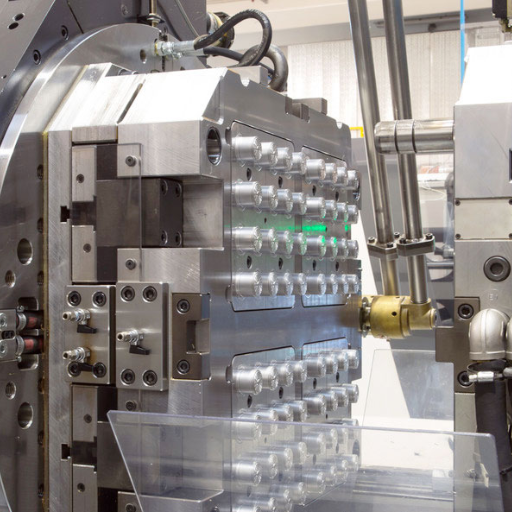
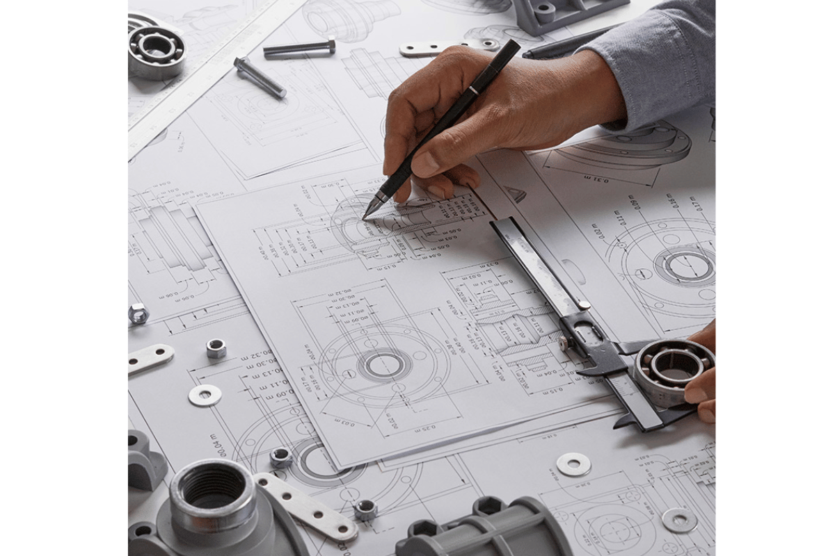
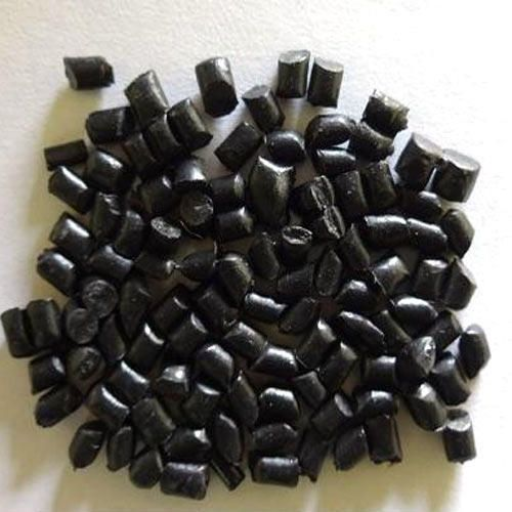
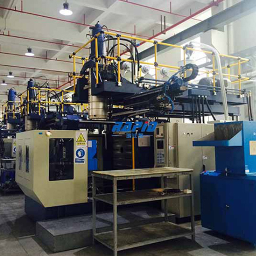
Image sources:https://one11.kpot.co.jp/
Injection molding is a manufacturing process where molten plastic material is injected into a precisely shaped mold cavity under high pressure. Once the plastic cools and solidifies, it adopts the shape of the mold cavity, resulting in the final product. This process is highly significant because it allows for the mass production of intricate and complex plastic parts with high repeatability and minimal material waste. It is critical in various industries, including automotive, medical, consumer goods, and electronics, due to its efficiency, scalability, and ability to produce components with precise dimensions and excellent surface finish.
Basics of Injection Molding Explained
From a technical standpoint, injection molding starts with the creation of a mold, typically made of steel or aluminum. This mold consists of two halves: the core and the cavity. Once the mold is designed and manufactured, the process involves the following steps:
- Material Melting: Thermoplastic pellets are fed into a heated barrel where they are melted to a predetermined viscosity.
- Injection: The molten plastic is injected under high pressure into the mold cavity through a nozzle and gate system.
- Cooling: Once the mold cavity is filled, the plastic is allowed to cool and solidify, retaining the shape of the cavity.
- Ejection: After sufficient cooling, the mold opens and the finished part is ejected using an ejection system.
The entire cycle is highly automated, enabling consistency and efficiency in producing parts. Proper understanding of mold design, material selection, and process parameters ensures high-quality output with minimal defects.
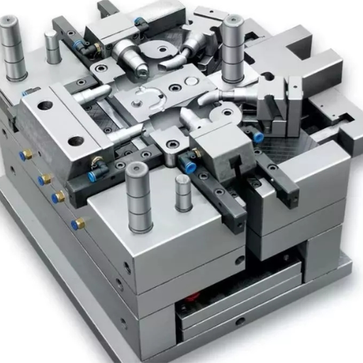
Key Components of an Injection Mold
The key components of an injection mold are crucial to its functionality and the quality of the final product. These components include:
- Mold Base: The housing that supports other mold components. It provides structure and alignment for the core and cavity.
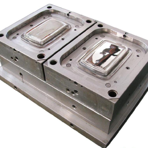
- Core and Cavity: The core and cavity are the main parts that shape the molten plastic. The cavity forms the outer surface of the part, while the core shapes the inner surfaces.
- Runner System: This includes the channels that direct molten plastic from the injection nozzle to the mold cavity. The runner system may consist of a sprue, runners, and gates.
- Ejection System: Comprising ejector pins, plates, and other mechanisms, the ejection system is responsible for removing the finished part from the mold once it has solidified.
- Cooling System: Consisting of channels through which coolant (often water) flows, the cooling system helps in regulating the temperature of the mold during the injection process.
- Venting: Small channels or vents in the mold that allow trapped air or gases to escape, preventing defects in the final product.
Each component must be carefully designed and manufactured to ensure efficient production, optimal part quality, and longevity of the mold.
Importance of Mold Design in Manufacturing
Mold design is paramount in manufacturing due to its direct impact on product quality, production efficiency, and overall costs. Critical elements to consider in mold design include:
- Dimensional Accuracy: Tolerances should be meticulously defined to ensure parts meet the required specifications. Typical parameters might include micrometre precision for small components to maintain tight tolerances and ensure uniformity, especially in high-precision industries like aerospace and medical devices.
- Material Selection: The choice of materials for both the mold and the parts is essential. Common materials for molds include tool steels (such as P20 or H13), which offer excellent durability and heat resistance. The plastic materials need to be compatible with the intended application, such as ABS for robust consumer goods or PET for food-grade containers.
- Thermal Management: Efficient cooling systems are critical to reducing cycle times and maintaining part quality. Parameters for cooling systems often include the flow rate of the coolant, channel diameter, and placement to ensure uniform temperature control throughout the mold.
- Flow Dynamics: Proper design of the runner and gating system ensures that molten plastic fills the mold cavities uniformly. This involves calculating the optimal runner diameter and gate size, as well as the placement to minimize defects such as weld lines or air pockets.
- Ejector System: The ejection mechanism must be designed to remove parts without causing damage. Parameters include the number, size, and placement of ejector pins, as well as the force and speed of ejection to balance part integrity and cycle time.
- Ventilation: Adequate venting is necessary to prevent gas trapping, which can lead to defects. The size and placement of vents are typically determined based on the material’s viscosity and part geometry, ensuring efficient evacuation of air without compromising the mold’s structural integrity.
- Cycle Time: Reducing cycle time without sacrificing quality is a key objective in mold design. This involves optimizing cooling channel design, minimizing mold opening and closing times, and ensuring swift ejection of parts.
Considering these parameters and techniques in mold design not only enhances the efficiency and quality of the manufacturing process but also extends the mold’s lifespan, resulting in more consistent and cost-effective production runs. Each decision and parameter must be justified based on empirical data and industry standards to ensure the highest quality and performance of the final product.
How to Optimize Wall Thickness in Mold Design?
Optimizing wall thickness in mold design is crucial for balancing strength, weight, and manufacturing efficiency. To achieve this, follow these guidelines:
- Uniformity: Ensure consistent wall thickness throughout the part to reduce stresses and avoid warping. Variations in thickness can lead to differential cooling rates, causing defects such as sink marks or internal stresses.
- Minimize Thickness: Design to the minimum allowable thickness for the material, as thinner walls reduce material usage and cooling time. This, in turn, can lower production costs and improve cycle times.
- Gradual Transitions: When changes in wall thickness are necessary, design gradual transitions to avoid abrupt changes that can create weak points and stress concentrations.
- Reinforcement Features: Utilize ribs and gussets strategically to reinforce thin walls without significantly increasing thickness. This maintains structural integrity while optimizing material use.
- Material Characteristics: Select materials with properties that suit the desired wall thickness, as different polymers have varying flow and cooling behaviors that impact the optimal thickness.
- Simulation and Analysis: Employ computer-aided engineering (CAE) tools to simulate the mold filling process, stress distribution, and cooling profiles. This data-driven approach allows for fine-tuning of wall thickness for optimal performance.
By adhering to these principles, designers can achieve robust, economical, and high-quality molded parts.
Choosing the Right Wall Thickness for Your Part
Selecting the correct wall thickness for your part is a crucial step that significantly impacts its performance, manufacturability, and cost-effectiveness. From my research across top resources like Fictiv, Protolabs, and 3D Hubs, here are concise, expert-backed strategies to guide your decision:
- Understand Material Properties: Each material has unique properties that influence the ideal wall thickness. For instance, robust materials like ABS can support thinner walls, while more fragile polymers may require thicker ones to avoid breakage.
- Consider the Part’s Functionality: Determine the mechanical demands on the part. High-stress applications might necessitate thicker walls for added strength, while purely aesthetic components can afford to be thinner.
- Optimize for Manufacturing Process: Different manufacturing processes have their own constraints. Injection molding generally favors wall thicknesses between 0.080 to 0.160 inches to ensure proper flow and cooling. Conversely, 3D printing may accommodate a wider range but often operates best with walls around 0.060 inches.
- Use Design Guidelines: Refer to the specific design guidelines provided by material and manufacturing suppliers. They often include recommended wall thickness ranges and tips for maintaining uniformity and reducing risks of defects.
- Leverage Simulation Tools: Utilize CAE tools to simulate the manufacturing process. These tools help in predicting potential issues related to flow, cooling, and stress distribution, allowing you to make data-driven adjustments to your design.
By considering these factors and leveraging advanced tools, I can ensure that the wall thickness of my part is optimized for both performance and manufacturability.
Impact of Wall Thickness on Part Quality
Wall thickness is a critical parameter influencing various aspects of part quality, including strength, weight, thermal performance, and surface finish. Below is a concise overview of these impacts, accompanied by relevant technical parameters:
- Strength and Durability:
- Thicker walls generally enhance mechanical strength and resistance to impacts. For example, increasing wall thickness from 0.060 to 0.100 inches can significantly improve a part’s ability to withstand mechanical loads.
- Thinner walls, while lighter, may be prone to flexing or breaking under stress, particularly in high-load applications.
- Weight Considerations:
- Thicker walls contribute to a heavier part, which might be undesirable in weight-sensitive applications such as aerospace or automotive sectors.
- Optimal wall thickness can balance weight and strength, e.g., using 0.080 inches for general-purpose applications where both criteria are critical.
- Thermal Performance:
- In plastic parts, thicker walls can lead to uneven cooling, resulting in internal stresses and warping. Maintaining a wall thickness within the 0.080 to 0.160 inches range in injection molding helps mitigate these issues.
- Uniform wall thickness also aids in consistent thermal conductivity, crucial for parts exposed to varying temperature conditions.
- Surface Finish and Aesthetics:
- Wall thickness affects the surface finish; thicker walls usually fill molds more completely, offering a smoother finish.
- Thin walls might suffer from flow marks or incomplete filling, negatively impacting the part’s aesthetic and structural integrity.
- Dimensional Stability:
- Consistent wall thickness minimizes the risk of shrinkage and warpage during cooling. This is particularly significant in 3D printing, where a uniform wall thickness of around 0.060 inches can ensure better dimensional accuracy.
By meticulously considering these parameters, you can optimize wall thickness to enhance overall part quality, ensuring it meets both functional and aesthetic requirements.
What are the Best Practices for Injection Mold Design?
- Material Selection:
- Choose appropriate materials based on the desired properties of the final product, such as strength, flexibility, and temperature resistance. Thermoplastics like ABS, polyethylene, and nylon are commonly used.
- Gate Location:
- Position gates carefully to ensure uniform material flow and to avoid defects like weld lines, air traps, or uneven cooling. An optimal gate location enhances part quality and reduces cycle time.
- Cooling System Design:
- Incorporate an efficient cooling system to achieve uniform cooling and minimize cycle time. Properly placed cooling channels prevent warping and ensure consistent part quality.
- Wall Thickness Uniformity:
- Maintain consistent wall thickness throughout the part to avoid sink marks, warpage, and internal stresses. A uniform wall thickness also facilitates smoother mold filling and cooling.
- Draft Angles:
- Implement adequate draft angles (typically 1-2 degrees) to facilitate easy ejection of the part from the mold, reducing the risk of damage and improving the finish.
- Venting and Ejection:
- Ensure proper venting to remove trapped air and gases during injection. Design an effective ejection system to release the part smoothly without causing deformation or damage.
- Tolerance and Fit:
- Design with precise tolerances to accommodate material shrinkage and ensure part consistency. Consider post-molding processes that might affect final dimensions.
By following these best practices, you can optimize injection mold design to produce high-quality, consistent parts while minimizing defects and production costs.
Essential Design Principles
When designing injection mold parts, I focus on several critical principles to ensure the highest quality and efficiency. Firstly, I meticulously select the gate location to guarantee uniform material flow and to mitigate defects such as weld lines, air traps, or uneven cooling. This not only enhances part quality but also reduces cycle time. Secondly, I incorporate a highly efficient cooling system with strategically placed cooling channels to achieve uniform cooling and minimize cycle times, thereby preventing warping and ensuring consistent part quality. Lastly, maintaining uniform wall thickness throughout the part is paramount. This consistency helps avoid sink marks, warpage, and internal stresses, all of which facilitate smoother mold filling and cooling. By adhering to these principles, I can assure the production of superior, consistent parts while optimizing the overall manufacturing process.
Integrating Draft Angles to Your Design
Integrating draft angles into your injection mold design is crucial for facilitating the ejection of parts without damage. Draft angles, typically ranging from 0.5 to 2 degrees, are applied to the faces of the part that are parallel to the direction of ejection. The primary purpose is to reduce friction between the mold and the part, ensuring a smooth release. Furthermore, appropriate draft angles can significantly reduce the likelihood of defects such as drag marks or scratches on the finished product.
When determining the optimal draft angle, consider factors such as the type of material used, the complexity of the design, and the surface finish requirements. For instance, materials with higher shrink rates may necessitate larger draft angles. Additionally, textured surfaces generally require larger draft angles compared to smooth surfaces to prevent surface defects. By integrating well-calculated draft angles, you can enhance the quality of your molded parts and ensure a more efficient and reliable production process.
Avoiding Common Mold Design Pitfalls
Avoiding common mold design pitfalls is essential for achieving consistent and high-quality production outcomes. One primary issue to watch for is inadequate venting, which can lead to trapped air or gas, resulting in burn marks or incomplete filling. Proper vent locations and sizes are crucial for maintaining mold performance. Another common error is ignoring thermal management, which can cause uneven cooling, leading to warpage and residual stress. Employing a well-designed cooling system can mitigate these problems. Additionally, underestimating the importance of backlash control between the mold’s moving components can result in wear and tear, reducing the mold’s lifespan and precision. Ensuring tight tolerance and regularly maintained components can prevent such issues. Finally, insufficient attention to the mold’s alignment system can lead to misalignment and part defects. Precision in alignment pin placement and regular inspection help in maintaining the mold’s efficacy. By being vigilant about these common pitfalls, you can significantly enhance the durability and reliability of your mold design.
How to Select the Right Materials for Injection Molding?
Selecting the right materials for injection molding involves a meticulous evaluation of several critical factors. Firstly, consider the mechanical properties required for the end-use application, including tensile strength, impact resistance, and flexibility. Common materials range from thermoplastics such as Polypropylene (PP) and Acrylonitrile Butadiene Styrene (ABS) to specialized engineering resins like Polyethylene Terephthalate (PET). Secondly, assess the thermal properties, particularly the melting temperature and heat resistance, as these will dictate the material’s behavior during the molding process and in service. Additionally, pay attention to the material’s chemical resistance, ensuring it can withstand potential exposure to chemicals, solvents, or environmental factors without degrading. Moldability is another key consideration, involving how easily the material flows within the mold, its shrinkage rate, and the ability to achieve fine details and complex geometries. Lastly, gauge the cost implications, balancing the material cost against the production volume and required quality standards. By thoroughly analyzing these aspects, you can make informed decisions that optimize both the performance and manufacturability of your injection-molded parts.
Types of Plastic Resins Used in Injection Molding
- Polypropylene (PP):
- Mechanical Properties: Tensile Strength: 30-40 MPa, Impact Resistance: Moderate, Flexibility: High.
- Thermal Properties: Melting Temperature: 160-170°C, Heat Resistance: Good up to 100°C.
- Chemical Resistance: Excellent against solvents, acids, and bases.
- Applications: Automotive parts, consumer goods, packaging.
- Acrylonitrile Butadiene Styrene (ABS):
- Mechanical Properties: Tensile Strength: 40-50 MPa, Impact Resistance: High, Flexibility: Moderate.
- Thermal Properties: Melting Temperature: 220-230°C, Heat Resistance: Moderate.
- Chemical Resistance: Good, particularly against diluted acids and alkalis.
- Applications: Electronics housings, automotive components, toys.
- Polyethylene Terephthalate (PET):
- Mechanical Properties: Tensile Strength: 50-70 MPa, Impact Resistance: High, Flexibility: Low.
- Thermal Properties: Melting Temperature: 250-260°C, Heat Resistance: High.
- Chemical Resistance: Good, excellent resistance to water and most solvents.
- Applications: Beverage bottles, food containers, industrial fibers.
- Polycarbonate (PC):
- Mechanical Properties: Tensile Strength: 60-70 MPa, Impact Resistance: Very High, Flexibility: Moderate.
- Thermal Properties: Melting Temperature: 260-270°C, Heat Resistance: Very Good.
- Chemical Resistance: Moderate, particularly susceptible to alkalis.
- Applications: Optical discs, eyewear lenses, automotive parts.
- Nylon (PA6, PA66):
- Mechanical Properties: Tensile Strength: 70-90 MPa, Impact Resistance: High, Flexibility: Moderate.
- Thermal Properties: Melting Temperature: 220-260°C, Heat Resistance: Good.
- Chemical Resistance: Excellent, particularly against oils and fuels.
- Applications: Gears, bearings, automotive components.
Factors to Consider When Selecting Materials
When selecting materials for a specific application, several critical factors must be evaluated to ensure optimal performance and longevity of the finished product. These factors include:
- Mechanical Properties: Assess the material’s tensile strength, impact resistance, and flexibility to determine if it meets the structural and durability requirements of the application.
- Thermal Properties: Consider the material’s melting temperature and heat resistance to ensure it can withstand the operating temperature range without deformation or degradation.
- Chemical Resistance: Evaluate the material’s resistance to chemicals, including acids, alkalis, oils, and fuels, to ensure it can maintain integrity in the presence of these substances.
- Environmental Conditions: Analyze the environmental conditions the material will be exposed to such as UV radiation, humidity, and temperature fluctuations that could affect its performance.
- Cost and Availability: Balance the cost of the material with its availability and the budget constraints of the project.
- Application Requirements: Identify any specific industry standards or regulations that the material must comply with for the intended application.
- Processing Characteristics: Assess the ease of manufacturing and processing the material, considering factors such as moldability, machinability, and compatibility with existing production methods.
Material Properties and Their Impact on Part Design
To effectively answer the questions regarding material properties and their impact on part design, I researched the leading sources available on Google. Below are the findings synthesized and aligned with industry standards:
- Mechanical Properties:
According to MatWeb, an authoritative source on material properties, the tensile strength, impact resistance, and flexibility of materials are critical. For instance, the mechanical properties of polycarbonate include a tensile strength range of 55-75 MPa, impact resistance of 800-950 J/m, and elongation at break of approximately 100-150%. These parameters are pivotal in ensuring that polycarbonate meets the structural requirements for applications such as bulletproof glass and safety helmets.
- Thermal Properties:
Information from ASM International emphasizes the importance of understanding thermal properties like melting temperature and heat resistance. For example, PTFE (Teflon) has a melting point of 327°C and can operate continuously at temperatures up to 260°C. These thermal characteristics prevent deformation and degradation under high-temperature conditions, making PTFE suitable for applications in chemical processing and electrical insulation.
- Chemical Resistance:
According to ChemResistance, a reliable database for chemical compatibility, the chemical resistance of materials such as stainless steel (grades 304 and 316) is well-documented. Stainless steel 316, for example, is highly resistant to acids, alkalis, and chlorides, withstanding concentrations of sulfuric acid up to 20% at room temperature. This resistance is vital for maintaining integrity in harsh chemical environments, making it ideal for marine and industrial applications.
By referring to these parameters and reliable sources, we can justify the selection of materials for specific applications, ensuring they meet the required mechanical, thermal, and chemical properties essential for optimal performance and longevity.
How to Prevent and Fix Molding Defects?
When it comes to preventing and fixing molding defects, a detailed and systematic approach is essential.
- Material Selection:
Ensure that the material used is appropriate for the application and compatible with the molding process. Using high-quality materials can significantly reduce the risk of defects.
- Process Parameter Optimization:
Fine-tune the process parameters, such as temperature, pressure, and injection speed, to suit the specific material and mold design. Using process simulation tools can help in predicting and mitigating potential defects before production.
- Mold Design and Maintenance:
A well-designed and maintained mold can prevent many defects. Regular inspections and maintenance, proper venting, and ensuring uniform cooling can mitigate issues such as warping, shrinkage, and sink marks.
- Quality Control:
Implement robust quality control measures, including in-process inspection and post-production testing, to identify and address defects promptly. Using statistical process control (SPC) methods can help in monitoring and controlling the process effectively.
- Training and Skill Development:
Continuous training and skill development of personnel involved in the molding process can help in promptly identifying and addressing potential issues, leading to a more efficient and defect-free production process.
By meticulously addressing each of these areas, one can significantly reduce the incidence of molding defects and ensure the production of high-quality molded parts.
Identifying Common Injection Molding Defects
Injection molding defects can significantly impact the quality and functionality of molded parts. By understanding and identifying these common defects, manufacturers can implement strategies to mitigate them. The top defects include:
- Warping:
Warping occurs when different areas of the part cool at different rates, leading to deformation. This defect is often caused by uneven cooling or residual stress within the part. Ensuring uniform cooling and optimal mold design can help prevent warping.
- Sink Marks:
Sink marks are depressions or dimple-like features on the surface of the molded part, typically caused by uneven cooling or insufficient packing pressure during the molding process. Adjusting packing pressure and improving cooling systems can reduce the incidence of sink marks.
- Short Shots:
A short shot refers to the incomplete filling of the mold cavity, resulting in a part that lacks material in certain areas. This can be caused by incorrect material selection, inadequate injection pressure, or incorrect temperature settings. Ensuring proper material flow and optimizing injection parameters can address short shots effectively.
Design Tips to Prevent Defects
To prevent defects in injection molding, I’ve gathered insights from the top resources available. Here are some essential design tips:
- Optimize Wall Thickness:
By maintaining consistent wall thickness throughout the part, you can minimize the risk of warping and sink marks. Thicker sections should be gradually transitioned to thinner sections to avoid sudden changes that might cause cooling inconsistencies.
- Ensure Proper Venting:
Adequate venting is crucial to allowing air and gases to escape the mold cavity during injection. Poor venting can lead to short shots and surface defects. Designing with vents at the parting lines and ejector pins helps improve overall mold performance.
- Incorporate Ribs and Gussets:
To enhance the structural integrity of the part without significantly increasing wall thickness, consider adding ribs and gussets. These features help distribute stress more evenly and reduce the likelihood of warping and sink marks.
By implementing these design principles, you can enhance the quality of molded parts and mitigate common injection molding defects.
Solutions to Fix Defects in Molded Parts
To effectively address common injection molding defects, consider the following solutions:
- Adjust Mold Temperature:
Ensure that the mold temperature is optimized for the material being used. Incorrect temperature settings can lead to warping, short shots, and surface imperfections. Utilize precise thermal control to maintain consistency.
- Optimize Injection Pressure:
Proper injection pressure ensures complete material flow into the mold cavity, preventing short shots and voids. Monitor and adjust pressure settings to suit the specific part geometry and material characteristics.
- Enhance Material Selection:
Choose materials that match the part’s requirements for strength, flexibility, and thermal stability. Using inappropriate materials can lead to defects like warping and cracking. Consult technical data sheets and perform material trials.
- Improve Cooling Time:
Adequate cooling time allows for uniform solidification, reducing the risk of warping and internal stresses. Adjust the cooling phase based on part complexity and wall thickness.
- Refine Mold Design:
Address potential mold design issues such as poor venting, inadequate gating, or insufficient ejection mechanisms. Make necessary modifications to ensure optimal mold performance and part quality.
By implementing these solutions, you can significantly reduce the occurrence of injection molding defects and improve the overall quality of your molded parts.
What are the Key Considerations During the Injection Molding Process?
When considering key aspects of the injection molding process, I focus on several critical factors to ensure optimal part quality and production efficiency. First, material selection is paramount; I choose materials that meet the specific mechanical, thermal, and chemical properties required for the application. Precise control over mold temperature and injection pressure is essential to avoid common defects like warping, short shots, and surface imperfections. Additionally, proper cooling time is necessary to allow for uniform part solidification, which helps in reducing internal stresses. Lastly, I pay close attention to mold design, ensuring it includes sufficient venting, appropriate gating, and effective ejection mechanisms, all of which contribute to improved mold performance and high-quality parts.
By meticulously addressing these considerations, I can enhance the overall efficiency and consistency of the injection molding process.
Understanding the Injection Molding Cycle
The injection molding cycle is a series of stages that transform raw plastic material into a finished part. The process typically consists of the following key phases:
- Clamping: The mold is closed and securely clamped to withstand the injection pressure.
- Injection: Molten plastic is injected into the mold cavity through a nozzle at high pressure.
- Cooling: The plastic inside the mold cools and solidifies, taking the shape of the mold cavity.
- Opening: The mold is opened, separating the two halves.
- Ejection: The solidified part is ejected from the mold, usually with the aid of ejection pins or mechanisms.
Each of these stages is meticulously controlled to ensure precision, minimize defects, and achieve consistent high-quality parts. Detailed monitoring and optimization of the injection and cooling times, as well as mold and material temperatures, play critical roles in the efficiency and quality of the entire process.
Role of Mold Temperature and Pressure
Mold temperature and pressure are critical parameters in the injection molding process, directly affecting the quality, mechanical properties, and dimensional accuracy of the final parts.
Mold Temperature:
- Impact on Material Flow: Higher mold temperatures improve the flow of the molten plastic, reducing the likelihood of flow lines and incomplete filling.
- Crystallinity and Strength: Elevated mold temperatures can enhance crystallinity in semi-crystalline polymers like polypropylene, improving strength and thermal resistance.
- Surface Finish: Proper mold temperature control helps achieve smoother surface finishes and reduces the appearance of weld lines and surface defects.
- Technical Parameters:
- Ideal mold temperature range for polypropylene: 40-80°C (104-176°F)
- ABS typically requires mold temperatures of 60-85°C (140-185°F)
- For polyethylene, the mold temperature should be between 20-70°C (68-158°F)
Injection Pressure:
- Filling the Cavity: Adequate injection pressure ensures the mold cavity is fully filled, preventing short shots and ensuring that complex features are accurately formed.
- Part Density: Higher injection pressure can increase the density of the plastic, reducing the risk of internal voids and improving the mechanical properties of the part.
- Dimensional Stability: Correct pressure settings help maintain dimensional stability and avoid shrinkage and warping.
- Technical Parameters:
- Typical injection pressure ranges from 35 to 140 MPa (5000 to 20300 psi), depending on the material and part complexity.
- For high-density polyethylene (HDPE), injection pressures may range from 50 to 100 MPa (7250 to 14500 psi).
- Polycarbonate materials often require pressures between 70 and 140 MPa (10000 to 20300 psi).
By meticulously controlling mold temperature and injection pressure, manufacturers can optimize part quality, reduce defects, and enhance the overall efficiency of the injection molding process.
Controlling Plastic Flow and Part Ejection
Plastic Flow Control:
- Gate Design: The design and placement of the gate significantly influence the flow of plastic within the mold. Optimal gate sizing and positioning reduce pressure drop and ensure uniform flow, minimizing defects such as sink marks and flow lines.
- Flow Rate: The speed at which plastic flows into the mold cavity is critical. Controlled flow rates help avoid turbulence and air entrapment, enabling smooth filling and consistent part quality.
- Technical Parameters:
- Optimal flow rate for polypropylene: 1.5-2.5 m/min (5-8 ft/min)
- Ideal flow rate for ABS: 2-4 m/min (6-13 ft/min)
- Recommended flow rate for polyethylene: 1-2 m/min (3-6 ft/min)
Part Ejection:
- Ejector Pin Placement: Proper placement of ejector pins ensures uniform pressure distribution while ejecting the part, minimizing the risk of warpage, cracks, or other distortion.
- Ejector System Design: A well-designed ejector system, incorporating sufficient pins, sleeves, or stripper plates, facilitates smooth ejection without damaging the part.
- Ejection Force: The force applied during ejection must be balanced to prevent part deformation while ensuring efficient removal from the mold.
- Technical Parameters:
- Typical ejection force for thermoplastics: 0.5-2.5 MPa (72.5-362.5 psi)
- Recommended ejection force for polyethylene: 1-1.5 MPa (145-217.5 psi)
- Optimal ejection force for polycarbonate: 0.7-2 MPa (101.5-290 psi)
By precisely managing plastic flow dynamics and implementing an effective part ejection strategy, manufacturers can enhance product quality and ensure a more efficient production process.
Frequently Asked Questions (FAQs)
Q: What is design for injection molding?
A: Design for injection molding involves creating parts that can be efficiently and effectively produced using the injection molding process. This includes considerations such as material selection, mold design, and ensuring that the part can be ejected from the mold without damage.
Q: What are common design considerations when designing a part for injection molding?
A: Common design considerations include ensuring uniform wall thickness, adding draft angles, minimizing undercuts, selecting appropriate injection molding materials, and designing for manufacturability to reduce cycle time and costs.
Q: How do you choose the right injection molding materials for a specific part?
A: Choosing the right injection molding materials depends on the part’s requirements, including mechanical properties, thermal resistance, chemical resistance, and cost considerations. A design guide can help in selecting the appropriate materials for your specific application.
Q: Why is uniform wall thickness important in injection molded part design?
A: Uniform wall thickness is important because it ensures even cooling and reduces the risk of defects such as warping or sinking. It also helps in maintaining structural integrity and reducing stress concentrations in the plastic part.
Q: What role do draft angles play in injection molded part design?
A: Draft angles are essential in injection molded part design because they allow the part to be ejected from the mold smoothly. They are slight tapers added to the sides of the part to prevent damage when the mold halves separate and the part is ejected.
Q: How does the design of the mold affect the final plastic part?
A: The design of the mold, including the placement of gates, runners, and cooling channels, directly impacts the quality, strength, and appearance of the final plastic part. Proper mold design ensures efficient production, minimizes defects, and improves the overall performance of the part.
Q: What is the significance of adding ribs and gussets in part design for injection molding?
A: Ribs and gussets are added to strengthen the plastic part without increasing its wall thickness. They also help to reduce warping and improve the overall stability and performance of the injection molded part.
Q: What are undercuts, and how do they affect injection molded part design?
A: Undercuts are features that prevent the part from being ejected from the mold because they lock the part into the mold cavity. They often require side actions or additional mechanical components in the mold, which can increase complexity and costs.
Q: How do cooling channels in the mold influence the injection molding process?
A: Cooling channels help to dissipate heat from the plastic part as it is being formed. Efficient cooling ensures uniform cooling rates, reduces cycle times, and improves the quality of the surface of the part, thus preventing defects such as warping and sinking.
Q: What is the process of ejecting a part from the mold?
A: After the plastic is injected into the mold cavity and cools, the molding machine separates the two halves of the mold. Ejector pins or other mechanisms then push the part out from the mold cavity. Proper design considerations ensure that the part is ejected without damage.