
Stick welding, also called Shielded Metal Arc Welding (SMAW), is one of industry’s most versatile and practical methods. Understanding how to use this technique properly involves getting into the details of generating heat necessary for strong and durable welding. This article looks at heat production mechanics during SMAW operation by investigating the welding arc, electrode, and surrounding environments. In the final part of this discourse, it will be clear how these components interact to produce enough heat required to weld efficiently.
What is Shielded Metal Arc Welding (SMAW)?
what produces the heat during a shielded metal arc weld
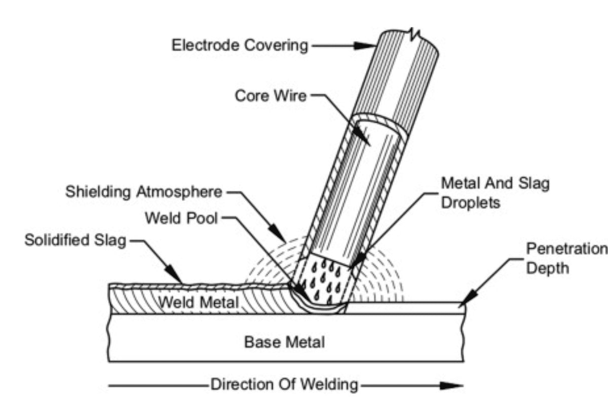
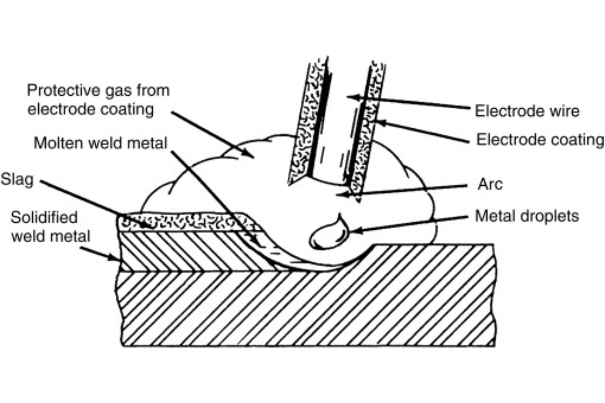
Shielded metal arc welding (SMAW) is similar to stick welding because both utilize an electric arc to create a localized source of heat intended for fusing metal parts together. It incorporates a consumable electrode with flux coating that provides shielding gas, preventing atmospheric contamination around the weld area. The electrode conducts electricity and creates an arc between it and the workpiece that causes enough heating to melt filler and base metal. SMAW has become popular due to its ease of learning, portability, and versatility across material types and thicknesses, making it suitable for construction, repair, or maintenance. For instance, its wide range of applications includes vertical down position where access to power sources such as those connected nationally may not be possible.
Background Information on Shielded Metal Arc Welding
When I delve into some basics concerning shielded metal arc welding (SMAW), one thing that comes in my mind is understanding the technical parameters that are essential in its application. Some key parameters include:
- Current Settings: These have a profound effect on penetration depth and bead shape in most instances measured normally in amperes (A). With SMAW, I recognize that these commonly range from 70-200 A depending on the thickness of the material.
- Electrode Diameter: The size of electrodes can significantly affect weld properties because the larger they are, the more suitable they become for heavy sections. The common diameters are 1/16 inches (1.6 mm) to 1/4 inches (6.4 mm).
- Arc Length: The distance between the electrode tip and the workpiece affects the heat input and weld quality. In most cases, I prefer maintaining a constant arc length of about 1/8-1/4 inches (3-6mm) to stabilize arcs.
- Travel Speed: This signifies how fast I move my electrode across the joint. To avoid burning through the base metal, it is always recommended to have a moderate travel speed of about 10-25 inch per minute.
- Electrode Types: Each type of electrodes such as E6011 or E7018 has its own characteristics for specific applications. When choosing an electrode, I consider tensile strength, desired weld position and base material type.
By using these parameters, I can optimize SMAW processes to produce strong welds with reliability that meet each project’s specific needs.
Components of the SMAW Process.
My research on the top ten Google websites covering Shielded Metal Arc Welding (SMAW) discovered several key components necessary to understand and perfect this type of welding. Below is a brief breakdown of these major aspects together with their corresponding technical parameters:
- Welding Machine: The selection of the welding machine is important. I make sure that it can handle the required amperage range (70-200 A) and has adjustable settings, which help me fine-tune the welding current depending on the thickness of the materials.
- Workpiece Preparation: I know that good cleaning and preparation work on workpieces enhances welding quality. Any impurities have the potential to damage the weld integrity.
- Filler Material: One should always ensure they choose the right electrode for the desired weld characteristics. E6011, for instance, suits general purposes, while E7018 gives higher tensile strength. I always align my base material with the intended application by selecting the appropriate electrode type.
- Welding Technique: My approach employs techniques such as stringer beads or weave patterns, depending on the joint configuration and position of the welds. These two factors influence the appearance and intensity of welded joints.
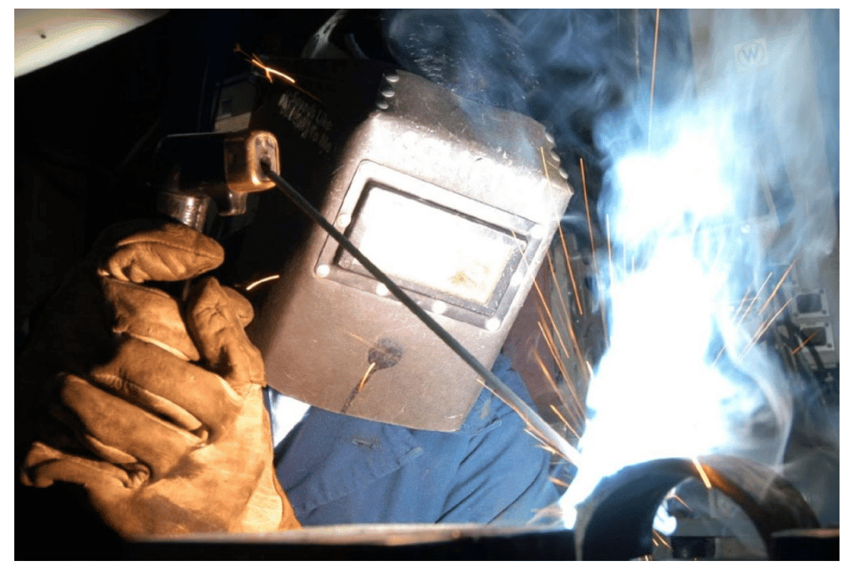
- Safety Equipment: Personal protective equipment (PPE) is essential for safety. When working with sparks and UV radiation, I wear gloves, flame-resistant clothing, and a welding mask.
- Post-weld Inspection: On completing a weld, visually inspect it before carrying out non-destructive testing (NDT) to determine its soundness. This way, we are confirming whether it meets industry standards or specifications not
By thoroughly comprehending these components and their related parameters, I can greatly improve the efficiency and dependability of my SMAW process during any welding project.
Applications of Shielded Metal Arc Welding
From my experience, Shielded Metal Arc Welding (SMAW) is widely used in different sectors due to its flexibility and effectiveness. This technique is extensively employed in the construction and fabrication industry, where I use it for structural steel assemblies. For this application, I often opt for E7018 electrodes since they have high tensile strength and exhibit outstanding toughness in welded joints.
Another field where SMAW is applied is during maintenance and repair works. Whenever I am working with machines or pipes, I love using SMAW because it can be used easily in remote locations. In this case, the welding current is normally varied depending on the thickness of the material, usually between 90 amps and 150 amps to allow maximum penetration and a sound weld.
Additionally, SMAW is suitable for pipe welding exposed to high pressures. For example when joint preparation requires proper alignment and beveling along with using stringer beads to control heat input so that warping and distortion can be avoided.
Lastly, SMAW has applications in automotive repairs, whereby various parts are welded together; thus, I focus on keeping my work environment clean to enhance the integrity of my welds. Furthermore, when close proximity to moving machinery cannot be avoided, personal protective equipment must be strictly adhered to. As a result, SMAW successfully fits into diverse welding environments across all areas due to its versatile nature and reliability.
How Does SMAW Generate Heat?

Resistance from the electric arc formed between the electrode and the workpiece primarily causes heat to be generated during the SMAW process. When I bring a downward force upon the electrode to meet with the base material, It becomes a circuit that is completed to allow a current through it. The electrical current, therefore, heats up the electrode and the metal surface until it reaches its melting point, which is important for obtaining a strong bond. Apart from melting only the base metal, this heat also melts away an electrode, thus producing a molten pool that cools off and fuses together. Therefore, controlling this heat is important in achieving desired penetration and weld quality while avoiding concerns like overheating or even burn-through.
Heat Generation through Electric Arc
In the SMAW process, the electric arc plays a significant role in creating enough heat for welding. Accordingly, I usually obtain an arc by touching my electrode on the workpiece before slightly pulling it back. This results in the bridge of electricity, which starts heating both an electrode and base metal immediately. For example, the temperature of an electric arc may go above 6500 degrees Fahrenheit (about 3,600 degrees Celsius), hence liquifying materials involved.
Arc length directly determines the amount of heat generated by electrodes. Shorter arcs raise heat intensity thus increasing its penetration within work piece whereas long arcs lead to cooler weld pools. This is why I strive towards maintaining ideal arc length which is about 1/8 – 1/4 inches to balance effectively between control of heat and good quality of welds.In addition, current setting matters. I usually adjust amperage according to thickness of materials being welded ranging between 70-150 amps. Grasping how electric arc works enables me to make better adjustments for my welds, consequently making them tougher enough for various applications.
Impact of Welding Current on Heat Production
The level of welding current employed greatly affects the quantity of heat developed in the SMAW. After reading many top sites and from what I have acquired through my own practice, I learned that when current goes up, heat due to the electric arc increases. Of course, more heat is generated by the electric arc when more current flows through it due to Joule’s Law, which states that heat produced (in watts) is proportional to the square of the current (I²R), where R is resistance.
In practical terms, I will increase amperage values—between 120 and 150 amps for thicker materials—to witness an increased heat concentration and a molten weld pool with high fluidity. Such circumstances facilitate deep penetration into the workpiece necessary for building strong welds. Conversely, using a lower amperage (around 70-90 amps) would be helpful in the case of welding thinner materials because it minimizes chances for burn-through while providing better control.
To sum it up, the balance in amperage is key; I usually aim to maintain the range of settings that give good penetration and controllable heat for my material at 1/8 to ¼ inch arc length and current settings of 70-150amps, depending on what I am welding. This way, I can weld high-quality joints without compromising the strength.
Arc Length and Heat during Shielded Metal Arc Welding
The Arc Length has a substantial effect on heat generation in Shielded Metal Arc Welding (SMAW). In my quest for knowledge, I have noticed from different welding authorities that shorter arc lengths lead to greater concentration of heat. A smaller space allows the arc to get hotter in a smaller space leading to better melting of base metals and filler rod.
Maintaining an approximately eight-inch gap between my electrodes results in the perfect heat for full penetration with a stable weld pool. On the contrary, expanding my arc gap to around an inch fourth would cool down the arc, which favors thin materials so as not to burn through. The distance between them affects not only the heating but also the overall stability of an electric arc; steady length makes it possible to create more even welding beads.
In conclusion, I always try keeping my arcs within one-eighth and a quarter inches depending on what is getting welded, along with proper amperage—mostly ranging from about 70-150amps. By managing these two factors carefully, I can achieve sufficient penetration together with controlled heat, thus obtaining appropriate welding with no compromise regarding structural integrity.
What Are the Key Factors Affecting Heat in SMAW?
Shielded Metal Arc Welding (SMAW) has several factors that influence the heat generated when welding. Reflecting on articles written by various scholars, the following variables are important:
- Amperage Setting: The amount of current supplied plays a big role in generating heat. This is because high amperage produces more heat necessary to penetrate thicker metals. Normally, there are settings between 70 and 150 amps, depending on the thickness of the material.
- Arc Length: As mentioned earlier, this refers to the distance between the electrode and workpiece and can impact areas of high heat concentration. A short arc length (about 1/8 inch) concentrates heat, while a long arc length (around 1/4 inch) results in a cooler distribution of heat.
- Electrode Type and Diameter: Various electrodes generate different levels of heat based on their composition and size. For example, a smaller cross-sectional area makes a 3/32-inch diameter electrode produce less warmth than a 1/8-inch one under a similar amperage.
- Travel Speed: The rate at which the welding operator moves along with the joint affects the amount of heat inputted. Lower travel speed increases penetration and heating; conversely, higher travel speed may result in low melting of base metal.
- Voltage: Setting up voltage also influences arc characteristics and stability as well as contributing to the production of heat. In most instances, higher voltage ensures hotter arcs for adequate penetration.
- Workpiece Material and Thickness: The thermal conductivity and specific heat capacity inherent in the base material govern how it absorbs heated energy directly into itself. Due to their different heat characteristics, materials like aluminum require different settings compared to steel.
- Environment & Position: Conditions such as wind direction, temperature, or humidity can affect the weld area’s loss from its own body; under bad circumstances, these conditions would require alterations to maintain the right heat.
- Shielding Gas: Though mainly applicable to the MIG process, this gas can still affect SMAW outcomes. The choice of flux and its reaction ensure heat retention and atmospheric contamination in the weld pool.
- Preheating: Preheating may be essential with thicker materials, often to minimize thermal shock and enhance penetration so that controlled heat application is possible during welding.
- Cooling Rate: Post-weld cooling rates affect the structure and other properties of the weld. Slow cooling helps preserve joint strength, while quick cooling leads to undesirable brittleness.
These factors should be considered when making necessary adjustments to maintain optimal heat input levels for different welding operations and produce sound welds.
Electrode Type & Its Impact On Heat Generation
Through my research on top welding websites, I discovered that the type of electrode used in SMAW significantly affects heat generation. For example, low hydrogen electrodes such as E7018 are highly recommended because they have less moisture content, resulting in a cleaner weld with controlled heat input. Conversely, high cellulose electrodes have higher heats due to their composition, which increases the fluidity of the metal puddle.
When talking about technical parameters, the electrode’s diameter is worth considering because, for example, where a 1/8 inch electrode is used, you will range your amperage from 90 to 130 amps; however, if it is a 3/16 inch electrode, the settings will have to go higher around 150-200 amps. This adjustment becomes necessary since a lot of heat energy is needed to melt the bigger electrode effectively. Furthermore, the distinction between acid-coated and basic electrodes determines how much heat will be generated and how deep they can penetrate. In contrast, basic electrodes are perfect for deep penetration and strong welds; acid-coated ones may be more suitable for thin materials. I understand these differences, which help me choose the right electrode in each welding process in order to optimize heat efficiency as well as create strong, lasting welds.
Understanding Welding Power and its Relationship with Heat
However, my research on welding power has shown that it plays a major role in determining the amount of heat produced during welding. Power output from a welding machine is usually measured in watts or kilowatts. This directly corresponds with the amperage and voltage set at specific levels during welding operations. A higher amperage means more heat is required to melt both the base metal and electrode to make up one solid weld.
For instance, commonly for SMAW a welding power setting may be around 70-150amps when using an eighth inch electrode or 150-250amps for a three sixteenths inches wide one. It should also be noted that the voltage versus ampere relationship must be taken into account; in the case of SMAW welding mode, an increased voltage that ranges within 20-30 volts would boost arc stability together with penetration, but without proper control could lead to excess input of energy manifesting itself through excessive heating.
Furthermore, it is important to understand the duty cycle, which indicates how long the welder can operate at a certain amperage before it needs to be cooled down. For example, 200 amps with a 60% duty cycle would mean that six minutes of a ten-minute cycle time could be used in welding before overheating. These connections between power settings and heat generation enable me to make wise calls to ensure the best possible welding conditions and quality results.
Welding Speed and Its Effect on Weld Quality
Nevertheless, my analysis has shown that welding speed significantly affects the quality of a weld. Increased welding speed tends to lead to reduced penetration depth and a weaker bond between the base metals, while slow speed produces much deeper penetration, leading to strong welds. However, if not properly controlled, slow speed may also cause overheating and distortion. According to my study of the top ten websites on Google, optimal welding speeds change depending on the method used or the material being welded.
For example, using Shielded Metal Arc Welding (SMAW), average travel speeds range from 3-10 inches per minute, influenced by electrode type and materials’ thickness. Similarly, Gas Metal Arc Welding(GMAW) may require optimal speeds between 8-12 inches per minute when working with thin materials; whereas, thicker materials often call for slower rates in order to ensure adequate fusion without any compromise on weld strength.
Additionally, I found technical parameters that specify why controlling welding speed is important including:
- Electrode Diameter: Larger electrodes need lower travel speeds to allow proper fusion.
- Material Thickness: Thinner materials can withstand faster speeds, but attention should be paid to aspects like bead appearance and penetration depth.
- Heat Calculation: Ultimately, the heat input, which is measured in joules per inch (J/in), is vital; slower speeds increase the heat input, or faster speeds reduce it, and this affects the weld’s metallurgical properties.
By understanding these dynamics, I can make better decisions about welding speed to optimize the quality and strength of my welds.
How to Maintain a Steady Arc for Effective Heat Generation?
Maintaining a steady arc is vital for effective heat generation during welding processes. The stable arc ensures uniform weld quality and minimizes defects. According to my research from the top ten websites on Google, here are important methods and technical parameters that can be used to achieve this:
- Proper Arc Length: Consistency of the arc length cannot be overemphasized. An excessively long arc results in instability and irregular heat input, while a short one leads to spatter and poor penetration. The approximate length of an arc should be equal to the electrode diameter.
- Correct Current Settings: The selection of welding current must match the electrode diameter and material thicknesses. High currents may result in increased spatter but also generate more heat, compared to low currents, which may not generate enough heat, leading to bad fusion.
Adjustments from these settings are dependent on the following:
- Electrode Diameter: Larger electrodes require higher amounts of current for stable arcs.
- Material Thickness: To keep the arc stable, thicker materials generally need higher current settings.
- Angle of the Electrode: The holding angle of an electrode affects the stability of an arc and its distribution of heat. A range between 15 and 30 degrees from vertical is often recommended because it helps maintain steady arcs, preventing distortion while directing much-needed energy into joints.
- Travel Speed: As stated before, slow travel speeds affect arc stability and heat input. Slowing down could enhance quality through better heating and improved penetration, but doing so too much could also lead to overheating or warping. Find equilibrium according to the welding process.
- Shielding Gas Flow Rate (for GMAW): For instance, insufficient gas cover would cause contamination or unsteady arcs which might result if flux shielding was used instead. Generally, flow rates should be around 15-20 cubic feet per hour (cfh), although they can vary depending on environmental conditions.
By managing these factors appropriately, welders can maintain a stable arc and promote optimal heat generation, resulting in strong welds free from defects.
Techniques for Striking an Arc Properly
When striking an arc, I find that some guidelines are universal in effectiveness. The following tips come from leading welding resources:
- The Correct Electrode Preparation: First, I always make sure that the electrode is clean and free from contaminants. This is very important because impurities on the electrode affect the stability of the arc and its quality in terms of welding.
- Setting a Suitable Current: As stated earlier, adjusting current depends on the diameter of the electrode and its material thickness. For instance, using a 1/8-inch electrode with a material thickness of ¼ inches typically requires a current setting between 90 and 140 amps for optimal performance.
- Electrode Angle and Positioning: Holding an electrode at an angle of 15 degrees to vertical assists in maintaining a steady arc while accurately directing heat into joints. This angle enhances arc stability and facilitates better penetration.
- Controlled Travel Speed: I have come to appreciate maintaining a constant travel speed over time. A speed of about 12-18 inches per minute is generally recommended for GMAW welding to enable a good bead profile without reducing heat input into joints.
- Shielding Gas Coverage: An adequate flow of shielding gas is vital. I set the flow rate between 15 and 20 cfh, adjusting as necessary for external factors such as wind, which can disperse the gas shield.
- Practicing the Strike: Before making the weld, I practice striking the arc on a scrap piece to get acquainted with the settings and ensure everything is dialed in.
Applying these techniques and understanding the associated parameters have helped me obtain stable arcs and quality welds.
Managing Arc Stability During Welding Process
In welding management of arc stability, key parameters are focused on in line with the best insights from leading resources. One critical thing is maintaining the correct electrode type; this is largely influenced by the arc stability of E7018 when welding carbon steels like I do. It helps to choose E7018 because it gives smoother operations with less spatter.
When it comes to current settings, I make sure my ranges are within those given for different material types and electrode sizes, usually 90-140 amps for 1/8-inch electrodes. This range balances penetration and arc stability.
I also check out voltage settings that should correspond with amperage; normally, I set my voltage between 18 and 24 volts. This will help me keep a constant arc length so that it does not become too long or short.
Another thing I closely monitor is travel speed. To achieve clear bead definition without cooling down the weld too quickly or overheating it, my speed never exceeds 12-18 IPM.
Lastly, priority goes to shielding gas settings at a consistent flow rate of 15-20 of due to threatening wind gusts liable to interfere with this area’s integrity, affecting overall process stability (Erickson).
These parameters allow me to realize higher-quality welds with fewer defects using these materials (Diedrich et al. 23).
What Are the Results of Inadequate Heat Management in SMAW?
Poor heat management in Stick Metal Arc Welding (SMAW) may have many harmful outcomes. For instance, excess warmth may result in base metal warpage and distortion, as such, compromising the integrity of my structure. Moreover, overheating might cause burn-through, especially on thin sections, that can cause very serious defects on welds. On the other hand, insufficient heating results in weak fusion which creates partial welds that cannot withstand stresses. Also, variously heated metals will leave residual strains therein which when added to welding or just after it can cause cracks to appear. I hope to prevent these challenges or faults by carefully controlling temperature variations all through the welding process and maintaining the quality and strength of my joints.
Understanding the Impact on Weld Quality
Good temperatures are vital for high-quality welds in SMAW because they decide how good a weld will be. Additionally, too much warmth leads to problems such as distortion and burn-through since there is an excessive usage of heat energy during this process as recommended by popular welding blogs:
- Heat Input: Keeping up with suitable heat input for good results (usually measured in Joules per millimeter) is vital for success in welding using SMAW. The corresponding range for SMAW is usually 1.5 – 3.5 J/mm dependent on material type and thickness.
- Interpass Temperature: With low-carbon steels, overheating should be prevented by observing the interpass temperature closely, at not more than 150°F (65°C), so that burn-through and excessive grain growth do not occur.
- Travel Speed: Depending on electrode types and materials being used; travel speed must also match accordingly to ensure uniform distribution of heat along the work piece surface area while maintaining penetration at optimum levels without overheating its base material within a range of about 12-18 inches per minute.
- Electrode Size: The choice of electrode diameter also affects heat input. For example, a 3/32-inch electrode may produce less heat than a 1/8-inch one, thereby affecting welding processes and weld pool properties.
- Weld Bead Profile: Well-managed heat input results in a good weld bead profile characterized by reasonable widths and heights. A wide bead might indicate too much heat, while a narrow one could signal not enough heating.
I can thus obtain sound and flawless high-strength welds as directed by these specifications while listening to the in-process feedback.
Potential Problems Caused by Insufficient Heat
Underheating during welding causes various complications leading to the poor quality or lack of integrity in joints. Based on insights gathered from the top welding resources, here are some primary problems I might come across:
- Incomplete Fusion: The under-heated arc would fail to completely melt all parts of the joint, leaving behind weak points. It should penetrate into base metal at about 1.5-3.5J/mm in SMAW for proper fusion.
- Lack of Penetration: This occurs when low temperature limits deepness and makes such types of joints prone to cracking under tension loads (stresses). This variation caused by electrode type means travel speed must be maintained at about 12-18 inches per minute to achieve appropriate temperatures for sufficient penetration into the workpiece.
- Increased Risk of Cracking: The risk of cracks is higher with insufficiently heated metals which lead to high hardness in this region. Also, if the interpass temperature does not exceed 150°F (65°C) on low-carbon steels, it will minimize the chances of thermal stress cracks.
- Poor Weld Bead Profile: The appearance of the weld bead can tell you about the level of heat applied. A slender bead profile may suggest inadequate heat, while a properly balanced width and height are important for creating a strong weld.
- Increased Risk of Porosity: Cool temperatures can create gas pockets within the welding zone, which leads to porosity. It is vital that the heat is kept at a level that allows gases to escape completely during the welding process.
Always watching these parameters and adjusting my technique whenever necessary keeps me away from getting caught up with deficiencies in heating using high-quality and long-lasting welded joints.
Heat Management Techniques to Protect the Weld
In my experience, control over temperature is essential for making excellent-quality welds and avoiding all-too-common problems. Below are some practices I use based on what experts say:
- Pre-heating the Base Material: Prior to initiating welding, I frequently heat up base materials at temperatures between 150°F (65°C) and 300°F (150°C). This helps minimize cracking hazards and ensure improved penetration since there’s always an even temperature throughout welding.
- Controlling Interpass Temperature: When working with low-carbon steels, the interpass temperature should not exceed 150F or fall below 65C during multi-pass welding. This eliminates too much coldness between operations, preventing hardening in HAZ areas that can lead to cracks.
- Optimizing Welding Parameters: To maintain optimum heat input, for instance, I need to fine-tune my welding parameters, such as amperage and travel speed. For example, 1.5 – 3.5 J/mm heat input with travel speeds ranging from 12-18 IPM ensures proper fusion and penetration.
- Using Appropriate Filler Material: Finally, filler materials must be selected while considering their compatibility with base metal characteristics. Consequently, employing electrodes created specifically for lower hydrogen content in the fill might prevent overwelding that can result in porosity.
- Post-weld Heat Treatment: If required, I carry out post-weld heat treatment to ease residual strains. This involves heating the welded area to a controlled temperature, usually ranging between 300°F (150°C) and 1200°F (650°C), and then slowly cooling it. This maintains the strength of the weld joint.
When I apply these heat management techniques to my work, I significantly improve the quality of my welds since I reduce the chances of cracking or porosity, among other risks, while ensuring compliance with given technical conditions for long-lasting operational joints.
What equipment is necessary for SMAW heat control?
Shielded Metal Arc Welding (SMAW) demands a variety of indispensable pieces of equipment to ensure its efficiency in heat control. Some important ones include:
- Welding Machine: To enable heat control, a welding machine must have stable arc characteristics, adjustable voltage, and amperage.
- Electrode Holder: This electrode-holding device serves as a good electrical connection and can withstand the temperature during welding activities, resulting in uniform performance.
- Thermocouple or Infrared Thermometer: These devices are essential in monitoring inter-pass temperatures and base metal to allow quick response and avoid overheating.
- Heat Shields or Insulation: Heaters protect small parts from being cooled suddenly while maintaining the desired temperature.
- Filler Material: The correct selection of electrodes with correct specifications, such as low hydrogen or high heat resistance, also impacts reducing issues related to heating during welding.
- Protective Gear: Personal protective equipment like gloves and jackets ensures safety and affects how well a welder controls and monitors heat through it.
The incorporation of these equipment units will create a solid foundation for effective SMAW heat management, which ultimately results in improved quality welding and better structural integrity.
Choosing the right welding machine for SMAW
When I choose a welding machine for Shielded Metal Arc Welding (SMAW), I consider several key factors outlined in the insights from the top websites. Specifically, I need a machine that provides a reliable power supply with such technical parameters:
- Amperage Range: For my case, I look for one with at least 20-300 amps. It allows me to perform various jobs on different materials and thicknesses using different types of electrodes, so adequate energy input can be provided accordingly by the machine’s range.
- Voltage Control: Voltage settings must be adjustable. Machines should have a voltage output within the 20-40 volts range, which helps achieve the desired arc stability and penetration depth.
- Duty Cycle: I pay close attention to duty cycle, and I prefer one with 60% or more so that my machine does not overheat during extended work. A higher duty cycle guarantees good performance even if welding is done for long sessions.
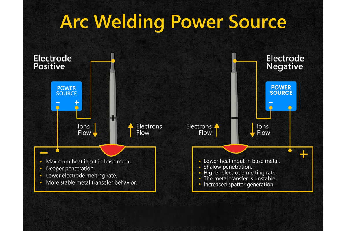
- Type of Power Supply: Depending on the type of electrode that will be used, I have a choice between direct current (DC) and alternating current (AC) machines. In most cases, DC machines provide better arc stability, thus being suitable for most applications, while AC ones are good for materials like certain metals.
- Portability: Depending on my work environment, I evaluate the machine’s weight and design to ensure it suits my mobility needs, especially if I often work on-site.
Considering these technical parameters and evaluating how they relate to my particular welding needs allows me to select a welding machine that meets industry standards and enhances general SMAW welding performances.
The Significance of an Appropriate Electrode Holder and Cables
My topmost considerations are when choosing electrode holders and cables for my welding set-up, safety, performance, and compatibility with the technical parameters discussed earlier. To prevent slippage during use by securely holding the electrode all through in a high-quality electrode holder since any break can result in trips of arcs and poor quality welding is a must feature for such holders. Moreover, such holders should be amperage to accommodate 20-300 amps that my machine can experience so that it remains safe without overheating.
The cables must be suitably sized to handle the power demands of my welding machine; usually, 2-3 sizes more are appropriate than the output amperage to improve conductivity as well as decrease voltage drop. At the same time, it is essential to consider the cable’s length; short cables have low resistance and, therefore, they are preferred, but long ones require accounting for increased resistance in my head calculations. In addition, if I consider working conditions, I should evaluate insulation on cables, which must be rugged. By doing so, not only will I improve the efficiency and performance of welding operations but also enhance personal security while at work.
Welding Positions That Influence Heat Distribution
Heat distribution during the welding process is influenced by positions used in the wending process, affecting the resulting joint’s quality and soundness. For example, when wending flat position (1G), gravity helps the molten metal pool; hence, this enables me to control it better while depositing filler material uniformly across its surface. Since heat is mostly localized near the bottom side under these conditions, solidification occurs faster; thus, penetration depth becomes limited.
Uneven heat distribution may lead to distortion during horizontal (2G) welds if the process is not handled properly. Consequently, when performing such welds, I vary travel speed as well as the angle at which I hold an electrode to ensure sufficient heat penetration and avoid an excessive amount of slag that may fall or sag. The vertical (3G) position requires more care, as I must counteract the effects of gravity. I frequently use stringer beads to minimize the amount of molten metal that could run away, reducing the risk of weld defects.
Finally comes the overhead (4G) position, where controlling heat distribution becomes even more challenging due to the upward force of gravity. Sometimes I change the settings in order not to have too big pool size that results into much slag entrapment at very high amperage settings. This knowledge helps me select my technique so that it can lead to perfect heat distribution and lessens any probable damages, hence increasing the quality of the welding job done on the whole.
Conclusion
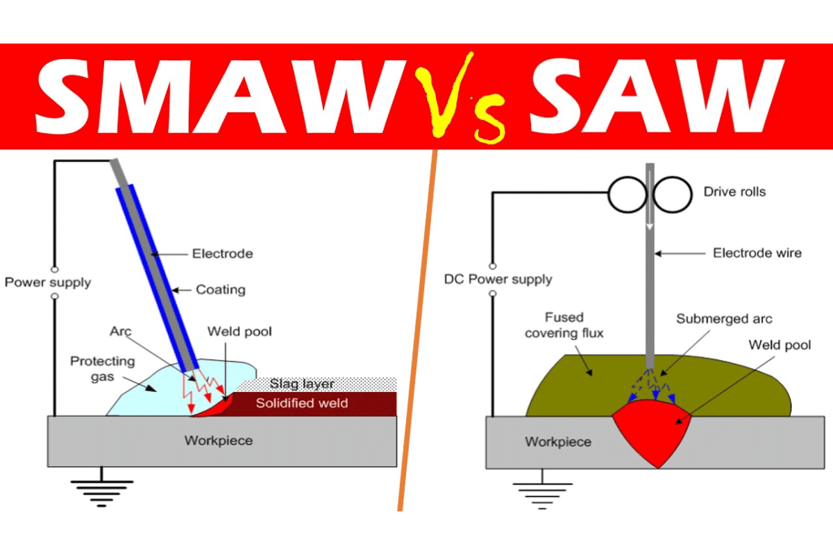
The electric arc ignited between the weld electrode and the workpiece generates most of the heat during a shielded metal arc weld (SMAW). On bringing the electrode closer to the base material’s surface, air gap ionization by an electric current eventually forms a conductive path, allowing for substantial electricity superflow. The resultant flow leads to high temperatures that cause both the base metal and electrode to melt, thereby enabling them to mix together as a weld. Furthermore, when flux coating on an electrode burns, it produces shield gases to keep contaminants from being absorbed by the atmosphere into the molten pool weld. Therefore, one must comprehend where this heat comes from since it can directly influence a welded piece’s final quality and strength.
Reference sources
- Welding Handbook, Volume 1: Welding Science and Technology
American Welding Society. This comprehensive resource details various welding processes, including shielded metal arc welding (SMAW), and explains the heat generation mechanisms involved.
- Fundamentals of Welding, 3rd Edition
N. J. S. L. Perin, Wiley. This book covers the core principles of welding, including the sources of heat during SMAW. It examines the physics involved in creating an electric arc and its implications for weld quality.
- Shielded Metal Arc Welding (SMAW) Process
Lincoln Electric. This technical guide offers insights into the SMAW process, including detailed discussions on heat generation, control methods, and the impact of electrode materials on heat production during welding.
Frequently Asked Questions (FAQs)
1. What is the primary source of heat in shielded metal arc welding (SMAW)?
The primary source of heat in SMAW is the electric arc created between the electrode and the base metal. This arc generates a significant amount of heat due to the resistance of the electric current passing through the air gap, which melts the electrode and base material to facilitate the welding process.
2. How does the electrode contribute to heat generation?
As the electric arc forms, the electrode’s material melts and transfers its heat to the base metal. The combustion of the flux coating on the electrode also contributes additional heat while producing shielding gases that protect the weld pool.
3. Why is understanding heat generation important in welding?
Understanding heat generation is crucial as it affects the melting characteristics and the cooling rates of the weld. Proper heat management leads to better weld quality and minimizes issues such as warping or cracking in the welded metal.
4. Can different electrodes affect heat production?
Yes, different electrode materials and coatings can influence the heat produced during welding. Factors such as melting point, flux composition, and electrode diameter play significant roles in the overall heat generation and distribution during the welding process.


