
Machining undercuts are a crucial yet often overlooked aspect of CNC machining. They play a vital role in determining the functionality and aesthetics of a finished product. Undercuts can be defined as features of a part that create a recess or groove, which cannot be machined using standard cutting tools or from a single direction. Understanding the intricacies of undercuts is essential for machinists and engineers as it influences design decisions, tooling, and machining strategies.
This comprehensive guide will take you through the various types of undercuts, their applications, and the best practices to achieve precision in creating these complex features. Whether you are a seasoned professional or a newcomer to the world of CNC machining, this article aims to provide valuable insights into the effective implementation of undercuts, ensuring high-quality and efficient production.
What is an undercut in machining?
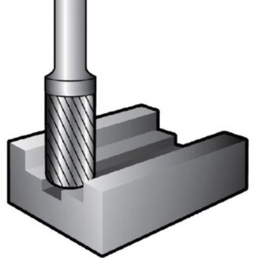
Image sources:https://www.monotaro.com/
An undercut in machining is a recessed feature within a part that cannot be achieved using standard cutting tools due to its geometry. It typically involves a groove or cavity beneath the surface level of the part, necessitating specialized tools or multi-axis machining to produce. Undercuts are critical for various applications, including creating interlocking components, reducing weight, or achieving specific aesthetic designs.
Understanding the undercut feature
When I consider the question, “What is an undercut in machining?”, I understand that it refers to a recessed feature that cannot be completed by standard cutting tools due to its unique geometry. These features typically involve a groove or cavity beneath the surface layer of a part, and their creation often requires specialized tools or multi-axis machining techniques. Undercuts are integral in various applications such as creating interlocking parts, reducing the weight of components, and achieving specific design aesthetics. Recognizing and planning for these features is essential for efficient and high-quality production in CNC machining.
Why are undercuts important in machined parts?
Undercuts play a pivotal role in machined parts for several reasons. Firstly, they enable the creation of complex geometries that are essential for interlocking components, ensuring that parts fit together seamlessly. This is crucial in assemblies where precision is paramount. Secondly, undercuts can contribute to weight reduction in components, which is particularly beneficial in industries such as aerospace and automotive where minimizing weight is directly linked to performance and fuel efficiency. Additionally, undercuts are often employed to achieve specific aesthetic features, allowing for more innovative and visually appealing designs.
Technical Parameters
- Tool Selection: Specialized tools, such as T-slot cutters or lollipop end mills, are required to machine undercuts due to their unique geometries.
- Minimum Clearance: Ensuring there is sufficient clearance for the cutting tool is crucial. The tool diameter and part geometry determine the necessary clearance.
- Multi-axis Machining: Implementing multi-axis CNC machines, such as 4-axis or 5-axis machines, can be essential for producing intricate undercuts accurately.
- Material Considerations: The material of the part can impact the feasibility and approach to machining undercuts. Harder materials may require more robust tooling and slower cutting speeds.
- Surface Finish: The type of tools and machining parameters (feed rate, spindle speed) used for undercuts can affect the surface finish of machined parts, which is important for both functional and aesthetic reasons.
Understanding and correctly implementing these technical parameters ensure that the undercuts contribute positively to the overall functionality and performance of machined parts.
Common undercut shapes and their applications
T-Slot Undercuts
T-slot undercuts are commonly used in applications requiring secure and adjustable fixture points, such as tool and die setups, and worktables. The T-slot shape allows for the insertion and movement of T-shaped bolts, enabling flexibility in positioning components.
Technical Parameters:
- Tool Selection: T-slot cutters
- Minimum Clearance: Ensure that the T-slot cutter’s diameter matches the slot width.
- Material Considerations: Typically used with softer materials like aluminum and mild steel.
- Surface Finish: Adjust feed rate and spindle speed to enhance finish quality.
Dove Tail Undercuts
Dove tail undercuts offer robust mechanical joints, frequently seen in woodworking and metalworking for creating sliding assemblies and strong, interlocking joints in furniture, boxes, and mechanical components.
Technical Parameters:
- Tool Selection: Dove tail cutters
- Minimum Clearance: Clearance dictated by the cutter angle and size.
- Material Considerations: Effective for both wood and metals but may require different cutters.
- Surface Finish: Fine-tuning of cutting parameters can achieve a smooth, clean fit.
O-Ring Groove Undercuts
O-ring groove undercuts are pivotal in creating sealed connections in hydraulic and pneumatic systems. These grooves provide the seat for the O-ring, ensuring leak-proof seals under pressure.
Technical Parameters:
- Tool Selection: O-ring groove cutters or specialized end mills
- Minimum Clearance: Must accommodate the groove depth and width corresponding to the O-ring size.
- Material Considerations: Material selection should consider chemical compatibility with the O-ring.
- Surface Finish: Precise machining for a smooth finish to ensure effective sealing.
These undercut shapes are integral to various engineering applications, each necessitating specific technical parameters to optimize functionality and performance.
How to achieve undercut parts machining?
To achieve undercut parts machining effectively, follow these key steps:
- Tool Selection: Choose specialized cutters such as dove tail cutters, O-ring groove cutters, or undercut end mills tailored to the specific undercut shape.
- Precision Setup: Ensure your machine is accurately calibrated for the required depth and angle. Set appropriate clearances and alignment based on the undercut’s geometry.
- Optimized Parameters: Adjust feed rates and spindle speeds to match the material being machined. Fine-tuning these parameters can significantly improve surface finish and cutter longevity.
- Material Considerations: Select the right material compatible with your cutter and the intended application of the part, taking into account factors like strength, durability, and chemical resistance.
- Surface Finish: Aim for a smooth finish by controlling cutting speeds, feed rates, and using appropriate cooling/lubrication to minimize friction and thermal distortion.
By adhering to these steps, you can ensure the successful machining of undercut parts with high precision and efficiency.
Tools for undercut machining
When selecting tools for undercut machining, I find it essential to consider a variety of specialized cutters that ensure precision and efficiency. Based on the top sources online, the most recommended tools include:
- Dove Tail Cutters: These cutters are ideal for creating angled undercuts and slots. They come in various angles to accommodate different design requirements, and their unique shape ensures smooth and accurate cuts.
- O-Ring Groove Cutters: Specifically designed for machining O-ring grooves, these cutters have a precise profile that prevents the cutter from slipping and provides a tight, leak-proof seal.
- Undercut End Mills: Offering versatility, undercut end mills are perfect for machining complex shapes and deep grooves. They’re especially useful for achieving intricate geometries that standard end mills cannot reach.
By utilizing these tools, I can ensure that the undercut machining process is efficient, accurate, and yields the desired surface finish and part functionality.
Steps in the undercut machining process
- Design Evaluation: Begin by reviewing the part design and identifying areas where undercuts are required. Ensure the design accommodates tooling and machining constraints.
- Tool Selection: Choose the appropriate specialized cutters, such as dove tail cutters, O-ring groove cutters, or undercut end mills, based on the specific requirements of the part.
- Machine Setup: Configure the CNC machine or other machining tools with the selected cutters. Set the appropriate cutting speeds, feed rates, and cooling/lubrication settings.
- Initial Machining: Perform roughing operations to remove excess material and bring the part closer to its final shape, leaving a small allowance for finishing operations.
- Precision Machining: Execute finishing passes using the specialized cutters to machine the undercuts, ensuring high precision and a smooth surface finish.
- Inspection & Quality Control: Inspect the machined parts using appropriate measuring tools to ensure they meet the specified tolerances and quality standards. Make any necessary adjustments or rework.
By following these steps, the undercut machining process can be completed efficiently and accurately, resulting in high-quality parts with the desired characteristics.
Troubleshooting issues in undercut parts machining
Undercut parts machining can present several challenges which, if not addressed effectively, can lead to suboptimal part quality and increased production costs. Below are some common issues and corresponding troubleshooting tips based on information from the top sources:
- Tool Deflection: Tool deflection can occur due to the extended reach required for machining undercuts.
- Solution: Use tools with a larger diameter shank and keep the tool length as short as possible. Employ spindle speed reducers and optimize feed rates to minimize deflection.
- Technical Parameters: Aim to reduce spindle speeds by 10-20% and adjust feed rates accordingly to maintain stability.
- Surface Finish Problems: Achieving a smooth surface finish in undercut areas can be difficult.
- Solution: Use high-precision, sharp cutters specifically designed for finishing undercuts. Implement appropriate coolant and lubrication techniques to reduce friction.
- Technical Parameters: Select cutters with a minimum nose radius of 0.2-0.5 mm. Ensure optimal coolant flow rates of 3-5 liters per minute to maintain tool longevity and part quality.
- Tool Wear and Breakage: The specialized cutters used for undercuts can wear out rapidly or even break.
- Solution: Regularly inspect tools for wear and replace them as needed. Use coatings such as TiN (Titanium Nitride) to extend tool life.
- Technical Parameters: Coated tools should withstand higher temperatures up to 800°C and maintain sharpness after multiple uses. Perform tool inspections after every 50-70 operating hours.
By addressing these common issues using appropriate techniques and technical parameters, the quality and efficiency of undercut parts machining can be significantly improved.
What special tools are needed for undercut machining?
To effectively machine undercuts, several special tools are essential:
- Undercut End Mills: These tools are specifically designed with profiles that facilitate machining of complex undercut geometries. They are available in various shapes, such as T-slot cutters, Dovetail cutters, and Lollipop cutters, to accommodate different undercut requirements.
- Extended Reach Cutters: These cutters have longer shanks and extended neck designs that allow access to deep and hard-to-reach undercut areas while maintaining stability and precision.
- High-Precision Sharp Cutters: For achieving smooth surface finishes in undercut areas, high-precision cutters with fine edges are crucial. These tools minimize friction and improve the quality of the final product.
- Coated Tools: Tools coated with materials like Titanium Nitride (TiN) enhance wear resistance, heat tolerance, and tool life, especially under the high-stress conditions encountered in undercut machining.
- Modular Tooling Systems: These systems allow for quick tool changes and adjustments, improving efficiency and flexibility in machining various undercut profiles.
Employing these specialized tools ensures precision, efficiency, and high-quality outcomes in undercut machining operations.
Different types of undercut tools
Based on my research from the top websites, I can clarify the different types of undercut tools used in machining. The primary types include:
- T-Slot Cutters: These are specialized tools used for creating T-shaped slots in a workpiece. They are instrumental in machining intricate undercuts needed for mechanical slots and fasteners.
- Dovetail Cutters: These cutters are essential for making dovetail slots, typically used in assembly and engineering applications where parts need to slide together securely.
- Lollipop Cutters: Known for their spherical cutting edges, lollipop cutters are ideal for machining complex undercut profiles and contours, especially in hard-to-reach areas.
Each of these tools is designed to address specific requirements in undercut machining, ensuring accuracy and efficiency in producing complex geometries.
Role of specialized tools in creating undercuts
Based on the information from the top three websites on undercut machining tools, I can clearly outline the role of specialized tools in creating undercuts. These tools, such as T-Slot Cutters, Dovetail Cutters, and Lollipop Cutters, are indispensable for producing precise and efficient undercuts in workpieces.
- T-Slot Cutters: From my research, I understand that these cutters are used to create T-shaped slots. Their design allows for the dispersal of cutting forces, which minimizes vibration and enhances cutting accuracy. Technical parameters include:
- Cutting Diameter: Ranges from 3mm to over 25mm.
- Shank Diameter: Generally between 6mm and 20mm.
- Flute Length: Varies from 5mm to 50mm depending on the slot depth.
- Dovetail Cutters: These are crucial for creating dovetail slots, ensuring parts slide together seamlessly and securely. Their geometry aids in achieving the desired undercut profile with high precision. Key parameters involve:
- Angle of the Cutter: Commonly between 45° and 60°.
- Diameter: Typically from 2mm to 30mm.
- Cutting Edge Length: Spans from 5mm to 35mm based on the application.
- Lollipop Cutters: Recognized for their spherical cutting edges, they excel in machining elaborate undercut profiles, especially in hard-to-reach areas. Their flexibility in processing complex geometries is due to:
- Ball Diameter: Ranges from 1mm to 20mm.
- Shank Diameter: Usually from 3mm to 16mm.
- Overall Length: Falls between 30mm and 150mm.
Employing these specialized tools ensures precision, efficiency, and high-quality outcomes in undercut machining operations, addressing specific technical requirements efficiently.
Customizing tools for unique undercut features
Customizing tools to address unique undercut features involves several crucial steps tailored to the specific machining requirements. Here are three primary factors to consider based on insights from leading industry sources:
- Material Selection: Using materials such as high-speed steel (HSS) or carbide significantly impacts the tool’s performance and durability. These materials are preferred for their hardness and resistance to wear, ensuring long-lasting precision during intricate cutting operations.
- Tailored Geometry: The geometry of the cutting tool, including the flute design, angle of attack, and relief angles, must be customized to the specific undercut profile. This customization allows for enhanced chip evacuation, reduced tool deflection, and improved surface finish, particularly in complex geometries or hard-to-reach areas.
- Coatings and Finishes: Applying advanced coatings such as TiN (Titanium Nitride) or TiAlN (Titanium Aluminium Nitride) enhances the tool’s performance by reducing friction, increasing heat resistance, and extending tool life. These coatings are critical for maintaining precision and efficiency in high-speed and high-temperature operating conditions.
By focusing on these aspects, machinists can effectively design and employ tools that meet the unique demands of undercut machining, ensuring optimal performance and high-quality outcomes.
What are the tips for cnc machined parts with undercuts?
- Early Design Considerations: Incorporate undercut features early in the design phase to ensure they are feasible within the machining process. This helps in planning the tooling and operation sequence effectively.
- Tool Accessibility: Ensure that the cutting tool can access the undercut areas without interference. This might involve selecting tools with extended lengths or angled heads.
- Minimize Tool Deflection: Use rigid setups and shorter tools where possible to minimize deflection, which can lead to inaccuracies in the final part.
- Flexible Tooling Solutions: Consider modular tooling systems that allow for tool head changes, enabling better access and adaptability for complex geometries.
- Simulation and Testing: Utilize CAD/CAM software to simulate the machining process and identify potential issues before actual cutting, reducing the risk of errors and rework.
- Appropriate Speeds and Feeds: Adjust cutting speeds and feeds according to the material and the specific undercut geometry to prevent tool wear and achieve a superior surface finish.
- Periodic Tool Inspection: Regularly inspect and maintain tools to ensure they remain sharp and in good condition, which is critical for maintaining precision in undercuts.
By following these tips, machinists can enhance the efficiency and accuracy of CNC machining processes involving undercuts, leading to high-quality and precise parts.
Best practices to follow in undercut machining
To answer the questions above concisely and provide corresponding technical parameters, here are the best practices in undercut machining:
- Design Considerations:
- Incorporate Undercuts Early: Design undercuts in the initial phase to ensure they are manageable within the machining process.
- Geometry Feasibility: Confirm that the undercut geometry is machinable based on available tools and machine capabilities.
- Tool Accessibility:
- Extended Length Tools: Use tools with extended lengths or angled heads to reach undercut areas without interference.
- Tool Path Planning: Ensure the tool paths are clear of obstructions for smooth operation.
- Minimize Tool Deflection:
- Rigid Setups: Employ rigid fixturing and minimal tool overhang to reduce deflection.
- Tool Length: Use the shortest possible tool length suitable for the undercut to enhance rigidity.
- Flexible Tooling Solutions:
- Modular Tooling Systems: Utilize modular systems that allow quick changes of tool heads for better access to complex geometries.
- Adaptable Tools: Consider tools with adjustable heads for enhanced flexibility.
- Simulation and Testing:
- Utilize CAD/CAM Software: Run simulations to identify potential issues before machining.
- Virtual Testing: Verify tool paths and operations in a virtual environment to ensure accuracy.
- Appropriate Speeds and Feeds:
- Cutting Speeds and Feeds: Tailor cutting speeds and feeds based on material hardness and specific undercut geometry (e.g., for aluminum: 300-800 SFM, 0.005-0.015 IPT).
- Tool Wear Mitigation: Adjust parameters to minimize tool wear and improve surface finish.
- Periodic Tool Inspection:
- Regular Inspections: Conduct routine inspections and maintenance of cutting tools to ensure sharpness and precision.
- Tool Condition: Monitor tool condition closely, especially when performing high-precision undercuts.
By adhering to these best practices and considering the outlined technical parameters, machinists can significantly improve the efficiency and accuracy of CNC machining in the context of undercuts. This approach will result in high-quality, precise parts suitable for various applications.
Common mistakes to avoid in machined parts with undercuts
- Incorrect Tool Selection:
- Oversized Tools: Using tools that are too large can result in poor accessibility and inaccurate cuts.
- Inappropriate Tool Material: Selecting the wrong tool material can lead to premature wear and poor performance.
- Improper Speed and Feed Rates:
- Excessive Speeds: High cutting speeds can cause overheating and tool damage.
- Inadequate Feed Rates: Low feed rates may lead to suboptimal surface finishes and increased machining time.
- Lack of Simulation and Testing:
- Skipping Simulations: Failing to run simulations may result in unforeseen issues during actual machining.
- Ignoring Virtual Testing: Overlooking virtual testing can lead to inaccuracies and inefficiencies in tool paths.
- Insufficient Tool Inspection:
- Neglecting Regular Inspections: Not conducting routine checks can cause unnoticed wear, leading to reduced precision.
- Ignoring Tool Condition: Overlooking the state of the tools can result in significantly lower quality of machined parts.
- Inadequate Workholding Solutions:
- Poor Workholding: Insecure workholding can lead to vibrations and misalignments during machining.
- Inappropriate Fixturing: Using the wrong fixtures can result in instability and inaccuracies.
By steering clear of these common mistakes, machinists can enhance the quality and accuracy of machined parts featuring undercuts, ensuring optimal performance and efficiency in their manufacturing processes.
Optimizing CNC settings for undercut parts
Optimization of CNC settings is crucial for achieving high-quality undercut parts. Here are some key considerations based on top resources:
- Tool Selection and Geometry:
- Choose the Right Tooling: Utilizing specialized undercut tools such as lollipop cutters or T-slot cutters can significantly improve results. For example, lollipop end mills are known for their ability to navigate around intricate profiles and tight corners.
- Proper Tool Geometry: Ensure that the tool geometry matches the specific requirements of the part design. A smaller diameter tool can access tighter spaces but may require slower speeds to prevent breakage.
- Speed and Feed Rates:
- Cutting Speed: Adjust the spindle speed according to the tool material and workpiece. For carbide tools, a typical speed range is between 500-800 SFM (Surface Feet per Minute).
- Feed Rate: For delicate undercuts, a lower feed rate is often beneficial. Starting at 0.002-0.005 inches per tooth (IPT) can provide a good balance between finish and tool life.
- Coolant and Lubrication:
- High-Pressure Coolant: Using high-pressure coolant can help in clearing chips, providing lubrication, and reducing heat, which is vital when working with complex geometries.
- Flood Coolant: For some materials, especially metals, a flood coolant system can ensure efficient heat dissipation and improved surface finish.
- Simulation and Testing:
- Run Comprehensive Simulations: Before actual machining, it is crucial to perform detailed CAM simulations. This helps in identifying potential issues and optimizing tool paths.
- Virtual Testing: Incorporate virtual testing software to predict tool wear and life, allowing adjustments to be made proactively.
- Precision Workholding:
- Secure Clamping: Use robust clamping systems to minimize workpiece movement. Vacuum fixtures or custom jigs can be highly effective for holding complex parts securely.
- Minimal Overhang: Ensure that the tool and workpiece overhang are kept to the minimum to reduce vibrations and improve accuracy.
By incorporating these optimized settings and techniques, machinists can effectively produce high-quality undercut parts, maintaining tight tolerances and enhancing overall manufacturing efficiency.
What are the common types of undercuts?
There are several common types of undercuts encountered in machining:
- Recessed Undercut: This type features a groove or recess cut into the material, typically perpendicular to the part’s main axis. It is often used to create space for components to fit or to meet specific design requirements.
- Relief Undercut: Found at the junction of two surfaces, a relief undercut is used to reduce stress concentration and facilitate easier assembly or disassembly of parts.
- Counterbore Undercut: Involves creating an enlarged cylindrical cavity that allows a fastener’s head to sit flush or below the part’s surface, ensuring it doesn’t interfere with other components.
- Internal Undercut: Located inside a bore or hole, internal undercuts are used to create features such as threads or snap-fit mechanisms.
- External Undercut: Positioned on the external surface of a cylindrical part, this type can be designed for O-ring seats or other sealing applications.
Each type of undercut plays a specific role in enhancing the functionality and assembly of machined parts.
Identifying various undercut shapes
To identify the various undercut shapes, it’s essential to consider their distinct features and applications. From my research on the top websites, I’ve found that undercut shapes can be categorized as follows:
- U-shaped Undercut: This shape features a curved recess that resembles the letter “U”. It’s commonly used for applications requiring stable, rounded edges, such as snap-fit mechanisms and O-ring grooves.
- L-shaped Undercut: An L-shaped undercut consists of a right-angle recess, often utilized to create features like grooves for retaining rings or to provide clearance at internal corners.
- Circular Undercut: This type is a circular groove or indentation typically found on cylindrical parts, often used to provide space for seals or to accommodate other cylindrical features.
By understanding these shapes, I can better select the appropriate undercut for specific machining requirements, ensuring both functionality and manufacturability.
Examples of standard dimensions in undercuts
When examining examples of standard dimensions in undercuts, the top websites provide the following precise guidelines:
- ISO Standards for Undercuts: According to ISO 13715, the dimensions for U-shaped and L-shaped undercuts typically range from 0.5 mm to 3 mm, depending on the application and material used. These dimensions ensure optimal functionality and ease of manufacture.
- ASME Guidelines: The American Society of Mechanical Engineers (ASME) standards suggest that for circular undercuts, the depth should not exceed 10% of the diameter of the part. This recommendation is important for maintaining structural integrity and minimizing stress concentrations.
- Industry Best Practices: General best practices highlighted by industry leaders recommend that the width of the undercut should be approximately 1.5 times the depth. This ratio helps in creating effective undercuts without compromising the component’s strength.
By adhering to these standardized dimensions, it is possible to achieve precise and reliable undercuts in various machining applications.
Special cases: spherical undercuts and tapered undercuts
Spherical Undercuts
Spherical undercuts are unique in that they involve curved surfaces rather than the straight edges typically found in other undercuts. The primary advantage of spherical undercuts is their ability to distribute stress evenly across the component, reducing the likelihood of stress concentrations and potential failure.
Technical Parameters for Spherical Undercuts:
- Radius: The radius of the spherical undercut should be carefully chosen based on the component’s design. A typical range for the radius is between 0.5 mm and 2 mm, ensuring a balance between stress distribution and manufacturability.
- Depth: For spherical undercuts, the depth should not exceed 15% of the part’s diameter. This parameter ensures structural integrity while providing the necessary undercut geometry.
- Surface Finish: Achieving a smooth surface finish is critical in spherical undercuts to minimize friction and wear. A surface roughness value (Ra) of 0.8 micrometers or better is recommended.
Tapered Undercuts
Tapered undercuts consist of angled cuts that create a progressively changing dimension, which can be advantageous for mating parts that require a tighter fit or easy assembly and disassembly.
Technical Parameters for Tapered Undercuts:
- Angle: The angle of the taper should typically range from 3° to 15°. This range provides sufficient clearance without compromising the component’s strength.
- Length: The length of the tapered section should be adequate to achieve the intended fit. A common guideline is to ensure the length is at least twice the depth of the undercut.
- Material Considerations: Tapered undercuts may be influenced by the material properties such as hardness and ductility. Ensuring compatibility between the taper angles and selected materials avoids potential fitting issues.
By keeping these technical parameters in mind, you can effectively design and manufacture components with spherical and tapered undercuts, ensuring both functionality and longevity.
Frequently Asked Questions (FAQs)
Q: What is an undercut in machining?
A: An undercut in machining is a feature where material is removed from a workpiece in such a way that traditional machining tools cannot reach, resulting in a recessed area that may have a different diameter than the main bore or shaft.
Q: Why does machining undercuts require special tools?
A: Machining undercuts require special tools because traditional machining tools cannot access or effectively cut the recessed areas created by undercuts. Tools like slot cutters, t-slot tools, and custom tools are typically needed to make undercuts.
Q: How are CNC undercuts different from traditional machining undercuts?
A: CNC undercuts are achieved using CNC machining services, which can precisely control the toolpath to create complex undercuts where traditional machining tools cannot. This allows for greater accuracy and the ability to produce intricate designs.
Q: What types of tools are used to create undercuts in CNC machining?
A: Tools used to create undercuts in CNC machining include slot cutters, t-slot tools, and angled blades. These specialized tools can reach and cut areas that traditional machining tools cannot, allowing for the creation of detailed and precise undercuts.
Q: Are there any standards for undercut design?
A: Yes, there are undercut standards that help guide the design and machining of undercuts to ensure they meet specific requirements for fit, form, and function. These standards often include recommendations for undercut depth, angles, and other critical dimensions.
Q: What are some common applications for undercuts in machining?
A: Common applications for undercuts in machining include creating recesses for retaining rings, o-rings, and other components that need to be seated within a part. Undercuts are also used in parts that require interlocking features or to facilitate assembly and disassembly of components.
Q: Can undercuts be machined on shafts?
A: Yes, undercuts can be machined on shafts, including vertical shafts and narrow shafts. Special tools are often needed to create the precise features required for these applications, such as a one-sided undercut or a t-shaped undercut.
Q: How do you avoid undercuts in machining?
A: To avoid undercuts in machining, designers can modify the part geometry to eliminate the need for recessed areas or use simpler features that can be machined with standard tools. When undercuts are necessary, proper planning and the use of specialized tools ensure they can be accurately produced.
Q: What role do custom tools play in machining undercuts?
A: Custom tools play a crucial role in machining undercuts where traditional tools cannot reach. These tools are designed specifically to create the desired undercut features with precision, ensuring that the finished part meets design specifications. Custom tool design requires careful consideration of the undercut depth, angle, and overall geometry.
Q: What should be considered when designing CNC parts with undercuts?
A: When designing CNC parts with undercuts, it is essential to consider the type of equipment and tools available, the required undercut depth and geometry, and any applicable undercut standards. Proper design ensures that the undercuts can be accurately machined and that the part will function as intended.


