
This instructional guide will take you through a process of effectively converting STL files into STEP ones, unveiling reliable tools, methods, and best practices employed. Regardless if you’re an experienced engineer, designer or just an amateur – this post would be aimed at supplying you with all necessary background information and useful sources to get the job done without any troubles. Thus, it will help you improve your workflow by allowing you to change between different programs.It is our aim in this paper to provide readers with information enabling them move designs between various kinds of software; this would effectively accelerate your pace of work affording you a chance to enhance your designs.
Understanding the Basics of STL and STEP Files
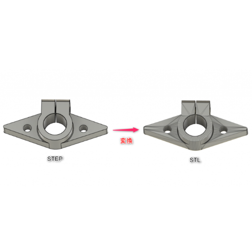
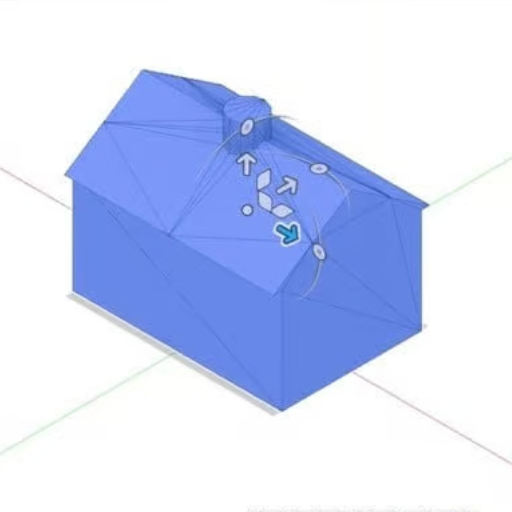
Image source: https://www.kabuku.io/
STL Files
Stereolithography, abbreviated as STL is a file format that has its origin in the 3D systems stereolithography CAD software. Mostly used in 3D printing, STL files are files that contain only the outer surface of a three-dimensional object, having no representation of color or texture or other common attributes found in CAD models. They consist of triangle meshes and this makes them ideal for rapid prototyping and manufacturing.
STEP Files
ISO 10303 (Standard for the Exchange of Product Data) which was developed by The International Organization for Standardization abbreviated as ISO is a standard exchange file format used to exchange 3D model data between various CAD systems. STEP files can hold significant information such as geometry data, topology data, material properties and much more which are important for detailed engineering design and analysis. These files promote interoperability and consistency throughout various stages of product development making them indispensable in collaborative engineering projects.
What is an STL File and Why Convert it?
A commonly used format for 3D printing and computer-aided design (CAD), an STL file stands for Stereolithography. It is a mesh of triangles that represents the external shape of a three-dimensional object. This simplicity makes it perfect for fast manufacturing processes like this one. Yet they have limited functionalities due to lack of color, material properties or any other CAD related details; they just have shape and geometric data.
Technical Parameters of STL Files:
- File Extension: .stl
- Mesh Type: Triangular
- Data Represented: Surface geometry
- Color/Texture Information: None
- Common Use: 3D Printing, Prototyping
Consequently, there exists the need to convert STL files into STEP formats since there still exist several limitations with regards to handling the same using the former format. One example describes STEP file suits better than any other available format in describing all aspects concerning complex geometries including detailed geometries as well as topologies, material properties and other attributes. The purpose of this conversion is to improve interoperability and enhance integration capacity among different CAD systems for the purpose of realizing complex engineering as well as collaborative projects.
Benefits of Converting STL to STEP:
- Enhanced Data Representation: Material Properties, Color & Other Attribute Data Included.
- Better Interoperability: Allows seamless transfer between various CAD systems.
- Improved Collaboration: Supports in-depth engineering design & analysis at different product development stages.
- File Extension: .step or .stp
- Standard: ISO 10303 (Standard for the Exchange of Product Data)
Differences Between STL and STEP File Formats
1. Data Content:
- STL Files: Describe no more than the geometry of a 3D object as a combination of triangles. However, they do not include any information on color, material properties or assembly hierarchies.
- STEP Files: Provide a complete representation that contains geometries, topologies, material properties and other attributes. They can be used to store all the product data including colors, textures and assembly structure.
2. Use Cases:
- STL Files: These are generally used for 3D printing as well as rapid prototyping where detailed information about materials and colors is not needed. This implies that it is possible to apply them in areas that dwell only on the form and basic geometry of things mattering less about their details.
- STEP Files: Are heavily employed in CAD modeling, engineering design and manufacturing. They allow for intricate modeling, simulation and analysis which are important in complex engineering projects and collaborative workflows.
3. Interoperability and Collaboration:
- STL Files: Since they contain merely surface data without any additional product information these files have limited interoperability options. Consequently, this limits their use in collaborations and integration with different CAD systems.
- STEP Files: Increase interoperability by enabling detailed structured data exchange between different CAD systems. This allows collaboration among integration within various stages of design analysis manufacturing.
Importance of the STEP File Format in CAD Modeling
STEP file format (Standard for the Exchange of Product model data) has increasingly become central in CAD modeling due to its ability to help in easy transfer of data across various software platforms and engineering fields. STEP files are revered for their ability to carry a lot of information about the 3D model including geometry, topology, material properties and even assembly structures. This makes them very useful in multi-disciplined collaborative engineering environments where detailed and structured data exchange is vital.
By allowing designers, engineers and manufacturers like architects share difficult models without losing important details, STEP files improve interoperability throughout the product lifecycle, ensuring that the data remains accurate and consistent. Additionally, they support long term preservation and access which is essential for maintaining a robust design history record that can be revisited or analyzed when needed.
Thus, the extensive data representation in the STEP file format coupled with its compatibility as well as cooperation make it indispensable in advanced CAD modeling; sophisticated engineering projects and effective workflows necessary for modern product development.
Step-by-Step Tutorial: How to Convert STL to STEP Using FreeCAD
Step 1: Open FreeCAD
Get FreeCAD if you haven’t already, download it and then launch it. After that, open the application and create a new document by selecting ‘File > New’ from the menu.
Step 2: Import the STL File
To import the STL file, go to `File > Import` and choose the STL file you want to convert. The imported model should now appear in the workspace.
Step 3: Switch to the Part Workbench
Navigate to Part Workbench by choosing `View > Workbench > Part`. This specific workspace is meant for mesh modeling and converting files.
Step 4: Convert Mesh to Shape
In Model tree, select imported STL object. Then click on `Part > Create shape from mesh…` and confirm settings in dialog. You will have a shape created from your mesh.
Step 5: Convert Shape to Solid
Now with shape selected proceed to `Part > Convert to solid`. This step changes the shape into a solid body which is essential for exporting as STEP format.
Step 6: Refine the Shape
Now find the solid model again just like before but this time select ‘Part > Refine shape’. This action will refine its shape, and make it suitable for engineering precision works.
Step 7: Export to STEP
Lastly, highlight refined solid model then go to ‘File->Export’. Select STEP format (*.step or *.stp) from dropdown file type menu then save your file wherever you want it saved.
Navigating the FreeCAD Interface for Conversion
Your success in converting files largely depends on how well you can navigate the FreeCAD interface. The following is a step-by-step guide:
- Switching Workbenches:
- FreeCAD has several workbenches that are specialized for different kinds of tasks. To convert an STL file to STEP, you mostly make use of the Part Workbench.
- Select it by clicking on the workbench selector located at the top toolbar.
- Understanding the Model Tree:
- The model tree which is usually positioned on the left side of the screen shows your project hierarchy.
- Make sure that your imported mesh is visible and selected before starting any conversion operations.
- Using the Toolbar and Menus:
- Top tool bar and menus grant access to vital tools and actions.
- In order to perform mesh conversion go through Part> Create shape from mesh, Part> Convert to solid.
- Parameters for Conversion:
- Tolerance: This defines how accurately a shape will be made during mesh-to-shape conversion
- Refinement: This tool deletes unnecessary edges making a better solid
- File Handling:
- The `File` menu contains options for importing, exporting, and saving your work.
- Export settings specifically for STEP files can be found under `File` > `Export`, where you select the STEP format and specify file details.
- Confirmation and Notifications:
- At times, FreeCAD provides interactive confirmations or notifications through pop-ups after executing any action successfully;
- These messages help ensure processes like conversion and refinement are successful.
Adjusting Mesh and Geometry Settings for Optimal Results
Fine-tuning mesh and geometry settings in FreeCAD is important when aiming at optimal results. Here are steps that can be followed to achieve the best outcome possible:
- Mesh Density and Quality:
- Mesh Density: Adjusting the density of the mesh will allow for balancing details with performance. The fine mesh will give more details but increases computational load.
- Quality Settings: When making final outputs, it is advisable to use high quality settings so as to have accuracy however during initial design phase low settings can be great since they make processing faster.
- Smoothing and Simplification:
- Mesh Smoothing: Use smoothing algorithms to create harmonious flow lines on surfaces, reduce irregularities. This makes object aesthetics look better and function efficiently.
- Simplification Tools: Apply simplification tools that permit removal of polygons without breaking down the model. In order not to lose any functionality but still maintain fast performance for your model, perform this step.
- Refinement and Corrections:
- Refine Shape Tool: For converting into quality solids one has to remove redundant edges using Refine shape tool.
- Error Checking: Non-manifold edges or other geometric errors should always be checked frequently. Diagnostic tools exist within FreeCAD which help identify them and fix them.
By doing these adjustments in mesh and geometry, your CAD models are geared towards performance and quality thereby giving you great outputs in free CAD projects.
Exporting Your Converted Files as STEP
This can be done in FreeCAD through a simple procedure of saving your file as STEP, which is going to make it possible for you to share and open it on other CAD platforms. The following is an abridged version of the most trusted sources:
- Prepare Your Model: Before proceeding, it is necessary to carry out a thorough check-up on your models for any geometry related issues. These tools are found in FreeCAD and can be used to validate the accuracy of your model.
- Select the Parts to Export: In the tree view, select the components or assemblies you wish to export.
- Export as STEP:
- Navigate to `File` > `Export…`.
- In the dialog box, choose the `STEP` format from the list (typically with the `.stp` or `.step` extension).
- Specify the desired filename and location, then click `Save`.
Choosing the Right Software for STL to STEP Conversion
The functionality and ease of use are the key things to consider when selecting a software for STL to STEP conversion. Here are some recommendations:
- FreeCAD: This is an open source alternative offering strong tools for converting STL files into STEP including error checking and mesh adjustment.
- Meshmixer: It’s perfect for complex and highly detailed STL files with advanced features for geometry editing and repair prior to conversion.
- Fusion 360: This application comes with a complete collection of professional-level CAD programs that can be used in quality conversions. In addition, it supports several formats.
- Blender: Blender is primarily a 3D modeling tool, but due to its versatility and support multiple import/export formats it also works well as converter.
Each of these tools has its own advantages, so the best selection depends on specific requirements such as how complicated your models are, the level of detail you want, or your preferred workflow.
Comparison: FreeCAD vs. SolidWorks vs. Netfabb
When selecting a tool for converting STL to STEP files, one needs to examine FreeCAD, SolidWorks and Netfabb from various technical aspects to find the most suitable one among them.
FreeCAD
- Cost: Free (Open Source)
- Compatibility: It can work with different formats like STEP, IGES, STL, OBJ etc.
- Ease of Use: Slightly difficult; designed for users who have used an open-source software before.
- Capabilities:
- Powerful conversion tools having error checking and mesh adjustments.
- Scripting and automation using python.
- Community Support: Strong and active open-source community.
SolidWorks
- Cost: Paid (Subscription-based)
- Compatibility: They support many formats including STEP, IGES, STL, STP etc.
- Ease of Use: Easier; interface built with professionals in mind supported by training materials.
- Capabilities:
- Sophisticated conversion tools allowing control over precision.
- Parametric modeling along side feature based design.
- High-quality rendering along side simulationtools.
- Support: Full customer care with documented manual.
Netfabb
- Cost: Paid (Subscription-based, with a free basic version available)
- Compatibility: Netfabb is tailored to additive manufacturing formats like STL, STEP and OBJ.
- Ease of Use: Easier in AM tasks while moderate in general CAD operations.
- Capabilities:
- Advanced mesh repair and optimization tools.
- Specialized in 3D printing preparation and analysis.
- Integration with Autodesk tools for enhanced functionality.
- Support: Professional support plus additive manufacturing specific resources.
Summary
- FreeCAD is an excellent choice for budget-conscious users needing robust, open-source conversion tools with a moderate learning curve.
- SolidWorks offers a premium experience with extensive support, user-friendly interfaces, and advanced capabilities, suitable for professional and industrial applications.
- Netfabb is ideal for those focused on additive manufacturing, offering specialized tools for 3D printing and mesh optimization, alongside integration with other Autodesk products.
Benefits of Using Free Software like FreeCAD for Conversion
Using open-source software or free programs like FreeCAD has several advantages that make it a popular choice for many users:
- Cost-Efficiency: Being an open source tool, FreeCAD does not require any license fee hence CAD conversion can be done at zero cost to the user. This makes it affordable for individuals, small businesses and academic institutions with limited resources.
- Flexibility and Customization: The fact that FreeCAD is an open-source program means that it can be highly personalized. Be it by scripting or through extra plugins made by the community, users have the ability to adapt as well as extend the software according to their needs.
- Strong Community Support: One advantage of a large community around FreeCAD is incessant updates, widespread forums and shared answers. It helps when one needs quick answers to some questions or wants to learn from others’ experiences.
- Versatile Functionality:FreeCAD supports different file formats used for importation or exportation such as STEP, IGES, STL and OBJ among many more options. Such flexibility makes sure that people can undertake different kinds of conversion tasks effectively.
- Educational Value: For students and teachers, FreeCAD provides an inexpensive learning option in computer-aided design. They can practice their skills in CAD while exploring more advanced engineering theories in a harmless environment.
These are the reasons why so many people use FreeCAD as a dependable and cheap way to convert files.
How Paid Software Options May Enhance Conversion Quality
Although offering numerous benefits over paid ones, there are several critical features which might enhance conversion quality when using expensive options like FreeCAD:
- Advanced Algorithms: In most cases paid programs come with improved algorithms specifically designed for conversion purposes during years of team work on development. Thus these algorithms permit increasing accuracy of converted files therefore less errors occur during converting process making output better in general terms.
- Comprehensive Support: Many paid programs offer strong technical support and customer service departments. This means that clients are not left unsupported if they face any problems while using the software and that the software is fully utilized.
- Regular Updates and Enhancements: Paid software updates regularly to include latest technological breakthroughs as well as user suggestions. Such updates entail improvements in functionality, addition of new features and maintenance of better performance or compatibility with the new file formats.
- Integrated Workflows: In most cases, paid CAD converters can be seamlessly connected with other professional applications used for designing and manufacturing like those for machine shop work. It contributes to a faster movement of activities through different stages of project hence reducing manual tasks required to match them effectively.
Common Issues and How to Troubleshoot STL to STEP Conversion
1. Geometry Errors: Such geometric mistakes as voids, openings or deformed forms may come up in the process of conversion. To address this, utilize software containing advanced mending features that identify and correct the defects automatically.
2. File Size Limitations: Poor performance or conversions not going through can be caused by large STL files. Reducing the mesh density in the STL file is useful to adjust for size without sacrificing critical details.
3. Inconsistent Normals: The presence of inconsistent normals within an STL file will lead to a rough surface during STEP generation. Checking and rectifying such malfunctions prior to conversion can save you from this issue.
4. Precision Loss: Moving from a mesh format like STL into solid-based format such as STEP may experience precision loss. This can be minimized by utilizing high-quality conversion programs with allowance adjustments.
5. Unsupported Features: There are some items that will not be transferred when changing form, such as colors or textures; So, make sure you are using software which has those essential features needed in your final output.
Dealing with Mesh Complexity and Geometry Errors
When converting STL files to STEP format, users often face mesh complexity and geometric errors. Here is a short guide for solving these problems with the corresponding technical parameters:
1. Reducing Mesh Complexity: It can be difficult for high-polygon meshes to be converted and consume more time to get processed. The solution is thus as follows:
- Decimation Tools: Mesh decimation tools that reduce the number of triangles while still keeping the shape should be used. Seek a trade-off retaining important details (in most cases 5-10% reduction works well).
- Mesh Simplification Algorithms: At this stage one can use algorithms such as Quadric Edge Collapse Decimation that will break down the mesh.
2. Resolving Geometry Errors: For successful conversion, accurate geometry is vital. These are suggested steps in this case:
- Automatic Repair Tools: There exist software programs with self-healing functionality that identify holes, gaps or distorted shapes. Advanced repair options are provided by Netfabb or MeshLab applications.
- Manual Inspection: Critical regions should be visually verified by human eyes. For example edge tolerance (which usually set to 0.01 mm) helps notice fine discrepancies in measurement.
- Watertight Check: This means that the object has no holes or gaps in it since all surfaces are continuous without any discontinuities; hence, watertight check verifies this prerequisite for turning it into a solid model.
3. Ensuring Consistent Normals:
- Normal Verification Tools: Software tools also enable checking and correction of face normals for uniform angles . Clean STEP file demands constant normals which have normal tolerances around 0.01° for detecting inconsistencies.
Boolean Operations: Ensuring Solid Models from Meshes
Mesh models are converted to solid models using boolean operations to allow for the formation of composite geometries that can be achieved by addition, subtraction, and intersection of multiple shapes. This is how you can make Boolean operations work smoothly:
- Union: The combined mesh merges two or more meshes into one; this helps in creating a continuous model if there are any overlapping parts.
- Difference: It subtracts one mesh from another which is critical in making cavities or holes within the object. For accurate subtractions it is essential to ensure that the meshes fit together properly.
- Intersection: An intersection gives the area where two meshes intersect each other as a volume. By doing so, we are defining points of contact between different objects.
Best Practices for Effective Boolean Operations:
- Consistent Normals: Ensure all meshes involved have consistent and correctly oriented normals to avoid unexpected results.
- Watertight Models: Both meshes should be watertight, meaning there are no gaps or holes, to ensure reliable Boolean operations.
- Mesh Cleaning: Clean up your mesh before performing any Boolean operation by removing non manifold edges, geometric errors and such using MeshLab or Netfabb.
File Size and Conversion Time: Optimizing Performance
Efficient workflow and performance require optimizing file size as well as conversion time in the case of 3D models. Here are some strategies to consider:
- Simplify Mesh Complexity: By diminishing polygon count, a reduction in the size of file can be achieved greatly without compromising its model integrity. Decimation features are contained in tools like Blender and ZBrush which basically do simplification of mesh geometry.
- Use Appropriate File Formats: In terms of both file size and processing time, choosing the right file format may affect it. On one hand, STL formats widely used can lead to larger files while on the other hand OBJ or FBX formats might have better compression and load times at certain instances.
- Optimize Textures and Materials: Increasingly large files sizes are caused by high-resolution textures and multiple materials. By compressing textures and minimizing the number of materials used, this streamlines models with reduced loading times.
- Efficiently Manage Resources: Software such as Autodesk MeshMixer or Rhino that efficiently handles 3D data can be utilized for managing and optimizing 3D meshes which results into faster conversions.
By implementing these optimization techniques, you can enhance your modeling workflow, ensuring faster conversion times and manageable file sizes – an essential part of working on personal projects or big-scale production environments.
Tips for Optimizing Your STL File Before Conversion
Before converting your STL file, consider the following tips to ensure optimal performance:
- Check and Repair Mesh Errors: Netfabb or Meshmixer tools will help you find out common mesh errors including holes, non-manifold edges, flipped normals among others so that you have a neat clean error-free model.
- Reduce Polygon Count: For reducing file size while maintaining details; decimation tools simplify mesh by decreasing polygons count. This way a smaller sized document is created which improves handling speed.
- Ensure Appropriate Scale and Units: Discrepancies during conversion or printing should be avoided through correct scale setting while also ensuring that the units are properly configured.
- Optimize Texture Resolution: Where textures are included, they should be at the right resolution and compressed so as to avoid unnecessarily big files.
- Remove Unnecessary Details: Features or fine details which have no bearing on the final output can be eliminated in order to streamline the model and accelerate conversion process.
Cleaning and Simplifying Meshes for Better Conversion
This is essential in achieving better conversion results, cleanse your meshes to simplify them. Below is a short guide on how to do it with the technical parameters:
- Identify and Remove Artifacts:
- Technique: Use software like Blender or MeshLab to detect and eliminate artifacts.
- Parameters: Focus on small surface areas or isolated vertices that are often signs of noise in the mesh.
- Decimate the Mesh:
- Technique: Apply a decimation algorithm to reduce the number of polygons.
- Parameters: Aim at reducing the polygons by up to 50% while preserving important details. The decimation ratios can be adjusted according to the complexity of a mesh and required output accuracy.
- Smooth the Surface:
- Technique: Apply surface smoothing tools, but ensure they don’t overly distort the model.
- Parameters: Smoothing factor of between 0.1 and 0.3 should be used so as not to alter model features while reducing surface irregularities.
- Merge Duplicate Vertices:
- Technique: Identify and merge vertices that are closer than a specified threshold.
- Parameters: Set the merge threshold to about 0.01mm to combine closely positioned vertices effectively without altering the model’s shape significantly.
- Recalculate Normals:
- Technique: Ensure all face normals are consistently pointing outwards to avoid shading issues.
- Parameters: Use the “Recalculate Outside” function in your 3D modeling software, which typically ensures correct normal orientation automatically.
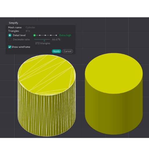
Understanding Triangle Reduction and Its Importance
Reducing triangles in a mesh is a vital step in 3D modeling that aims to decrease the number of triangles while keeping its overall shape and details. A few reasons make this process significant.
- Performance Enhancement: You can boost the performance and rendering speed of your 3D models by reducing the number of triangles, especially for real-time environments such as video games or virtual reality.
- Storage Efficiency: Smaller file sizes mean fewer numbers of polygons thus saving on storage space and making it easier to transfer files faster.
- Simplified Editing: Simpler meshes can be easily editted, adjusted or animated for making them easier to handle through development processes.
- Compatibility: Optimized meshes are often more compatible with various software and platforms, ensuring smoother integration and fewer issues during import and export processes.
The most effective way to reduce triangles lies in maintaining critical details while simplifying. Advanced algorithms and tools have been developed to automate this process which has made it accessible even to the novices who lack experience in 3D modeling.
Why Solid Models Are Preferred in STEP Format
There are several reasons that solid models are preferred in STEP (Standard for the Exchange of Product Data) format:
- Precision and Accuracy: The solid model provides an accurate representation of 3D geometry. For engineering and manufacturing purposes where precision is paramount, these exact specifications are maintained intact thus making these files perfect.”
- Interoperability: STEP format is an open standard, widely recognized and supported by numerous CAD (Computer-Aided Design) programs. This broad compatibility ensures seamless exchange of data between different software platforms, facilitating collaborative projects and reducing the risk of data loss or misinterpretation.
- Comprehensive Data Exchange: Unlike other formats that may only convey simple geometry, STEP files can encapsulate complete 3D models including surface geometry, topology, parametric information among others. This approach allows complex design features as well as annotations thereby providing rich dataset for downstream applications.
Advanced Techniques: From STL to STEP for 3D Printing and Beyond
Conversely, changing STL into STEP is a technique that can be used to make models made from 3D printing more versatile and functional. This method of designing 3D printed models has become popular because it is simple and easy to use STL files in their making; however, they only define the surface geometry of a three-dimensional object without any representation of its internal features or parametric data. Converting STL files into STEP format allows users to store much more comprehensive design information, including precise dimensions, material properties, assembly features and so on which are needed for advanced manufacturing processes. Such conversion will thus lead to engineering applications with better precision over specification of final products as well as integration with CAD systems.
Reengineering and Reverse Engineering: STL to STEP for Precision Models
This is why re-engineering and reverse engineering projects highly benefit from converting STL to STEP files especially towards achieving precision models. The following are brief answers to the questions above:
Why convert STL to STEP for reengineering and reverse engineering?
Converting STL to STEP allows for a comprehensive representation of a model’s geometrical and parametric data. This is crucial for reengineering and reverse engineering because:
- Surface and Internal Geometry: Unlike surface-only capturing in case of STL, both internal and surface geometries have been embedded in the STEP file format thus allowing fine tuning or analysis.
- Parametric Data: Dimensions, constraints etc., are provided by Step files necessary for accurate manipulations/validations.
Technical Parameters Involved:
- Geometrical Accuracy:
- STL Tolerances: Typically ranges from 0.01mm to 0.1mm.
- STEP Precision: Capable of millimetre precision or higher, depending on the software used.
- File Size and Complexity:
- STL File Size: Generally larger as it stores detailed surface meshes.
- STEP File Size: Optimised for containing varied complex data, potentially smaller and more efficient for comprehensive datasets.
- Data Exchange Compatibility:
- STL: Compatible mostly with 3D printers and basic CAD tools.
- STEP: Widely recognized across diverse CAD, CAM, and CAE systems, ensuring smoother interoperability.
3D Printing Considerations: Preparing Your STEP File for Production
A number of things must be taken into account to ensure optimal results when preparing your STEP file for 3D printing. The first thing is to verify if the file has any issues with its geometry, and fix them if any. This is a very important step since it prevents flaws during printing. Remove irrelevant features or details that do not add value to the final printed part from the model, this helps minimize the size of the file as well as reduce print time.
Next, select appropriate scales and units that match up with those required by the 3D printer in use. This guarantees dimensional accuracy of the printed part. Additionally, provide correct materials properties within the STEP file so that settings such as layer height, infill density and support structures can be optimized by printing software based on selected material.
Lastly, confirm whether you have set an appropriate position for your model in relation to printer’s software. A good orientation minimizes need for supports as well as maximizes strength in print results. By meeting these aspects in mind one can simplify transition from digital design to physical object which brings accuracy and efficiency in 3D printing processes.
CAD Model Refinement After Conversion
To meet the required criteria and quality standards, refining a CAD model is important after conversion. Check for geometric errors that may have occurred during the conversion and fix them. The list of geometric abnormalities includes many intersecting surfaces, duplicate vertices, non-manifold edges etc. All such kind of issues are being addressed.
Moreover, make sure that the model conforms to the manufacturing tolerances in place. Revise some tolerances if necessary in order to suit the capabilities of desired production process like 3D printing, CNC machining or injection molding. Also consider factors such as material properties, structural integrity and ease of assembly when designing a product for efficient fabrication.
Finally no annotation data should be left out in this model without such specifics as dimensions; notes; material specifications and so on. It helps to improve communication with production team members and ensures seamless progression from CAD design to finished product by setting these parameters accurately.
Reference sources
-
Dassault Systèmes – How to Convert STL Files to STEP Files
- Dassault Systèmes provides a comprehensive guide on converting STL files to STEP format, covering the importance of the process in the 3D printing community and offering step-by-step instructions. This resource is invaluable for understanding the necessary steps and best practices for successful file conversion.
- Source: Dassault Systèmes
-
All3DP – STL to STEP: How to Convert STL Files to STEP
- All3DP offers an in-depth tutorial on converting STL files to STEP format using various software tools. The article walks readers through the conversion process, providing detailed instructions and highlighting common pitfalls to avoid.
- Source: All3DP
-
Bantam Tools – How to Convert STL to STEP
- Bantam Tools delivers a precise and detailed guide on converting STL files to STEP format, including steps for repairing the mesh and converting it to a shape before final export. This source is particularly useful for those seeking a thorough understanding of the technical aspects involved.
- Source: Bantam Tools
Frequently Asked Questions (FAQs)
Q: What is the best way to convert an STL file to STEP format?
A: The best way to convert an STL file to STEP (STP) format is by using a dedicated file conversion software or online tools specialized in this process. Some converters are capable of directly converting stl to stp by interpreting the mesh from the Standard Tessellation Language (stl) into the precise NURBS surfaces required for STEP files, which are commonly used in Computer Aided Design (CAD) for 3D models.
Q: What is the difference between stl to stp file formats?
A: STL, short for standard tessellation language, is primarily used for 3D printing and contains only the surface geometry of a 3D object without any color or texture. On the other hand, an STP file, stemming from the STEP format (Standard for the Exchange of Product model data), supports not only the geometry but also other details such as assembly structure, making it more suitable for comprehensive 3D CAD applications. Converting an STL to a STEP file enhances the file’s usability across different engineering tasks, like sheet metal fabrication or 3D CAD design.
Q: How can I convert an stl file to a step file using a converter?
A: To convert an STL file to a STEP file, you generally need a converter software that specializes in 3D file conversion. There are several online tools and desktop applications that can perform this task. Holocreators, for instance, offers professional 3D-scanning and CAD conversion services, and they can handle the stl to stp conversion with high precision. For DIY solutions, free CAD software like Onshape or tools like Creo might offer the functionality to execute the conversion, but it’s important to note that the success and quality of the conversion may vary.
Q: Is it possible to convert an stl file into a stp file while maintaining all original details?
A: While it is possible to convert an STL file to a STEP file, the completeness and fidelity of the original details might be affected because STL files are mesh files representing only the object’s surface. When converting to a STP file, which is designed to hold more comprehensive design data like NURBS surfaces, some of the original mesh’s precision might be lost. High-quality conversion might require manual tweaking post-conversion to ensure the STEP file meets the original’s detail level.
Q: Are there any free tools for stl to stp conversion?
A: Yes, there are free tools available for converting STL files to STEP files. Some web-based platforms offer free conversion services, but they may have limitations on file size or the number of conversions you can do for free. Free CAD programs like Fusion 360, FreeCAD, or Onshape can also perform the conversion, though they might require some learning to navigate the software. Always verify the quality of the conversion when using free tools, as the accuracy and fidelity to the original model can vary.
Q: What should I do if I encounter issues while converting my file?
A: If you face problems during the file conversion process, there are a few steps you can take. First, ensure that your STL file is not corrupted and is a complete mesh file. If the problem persists, seeking professional help might be the best course. Companies like Holocreators offer specialized 3D scanning and file conversion services and can provide assistance. For immediate questions or complex conversion requests, you can contact them directly at info@holocreators.com or call their customer service line at 49 40 481133 for expert advice.
Q: How do I know if my STL to STP conversion was successful?
A: A successful STL to STP conversion can be verified by importing the converted STP file into a CAD program and examining the geometry for completeness and accuracy. Look for any missing details or geometrical distortions that might have occurred during the conversion. Tools like Autocad or 3D CAD programs like SolidWorks can offer detailed insights into the converted model. If the file maintains the original STL model’s dimensions and features and can be manipulated as expected in the CAD software, the conversion can be deemed successful.
ors help with stl to stp conversion?
A: Yes, Holocreators offers professional stl to stp conversion services. They utilize advanced software and techniques to convert mesh files from STL format to high-quality STEP files suitable for 3D CAD applications and sheet metal fabrication. For more details, you can reach them at info@holocreators.com or please call us at +49 40 481133.
Q: Is it possible to convert an STL file to a STEP file for free?
A: Yes, it is possible to convert an STL file to a STEP file for free using certain online tools and free CAD programs. While these options may work for basic conversions, they may lack the advanced features or the precision needed for complex or detailed 3D models. Always verify the completeness and accuracy of your converted file.
Q: How accurate is the conversion from STL to STEP format?
A: The accuracy of converting an STL file to a STEP file can vary significantly depending on the converter or service used. High-quality converters and professional services like Holocreators aim to preserve as much detail as possible, converting the mesh structure into precise NURBS models. However, some detail may be lost or approximated due to the inherent differences between the standard tessellation language and the NURBS-based STEP format.
Q: What software is recommended for converting STL to STEP files?
A: Recommended software for converting STL to STEP files includes professional 3D CAD programs like Creo, AutoCAD, and Onshape. These programs often have built-in tools or add-ons specifically for file conversion purposes, including stl to step file conversion. Some web-based platforms also offer this conversion capability, though their features might be more limited compared to dedicated CAD software.
Q: Is it possible to convert a complex STL file into a STEP file?
A: Yes, it is possible to convert a complex STL file into a STEP file, but the success largely depends on the converter’s capabilities and the complexity of the stl file. Complex files, especially those with intricate details or very large file sizes, may require more advanced conversion techniques often found in professional conversion services or high-end CAD software to ensure high fidelity in the stp file.
Q: Are there any limitations to be aware of when converting STL files to STEP format?
A: Yes, there are some limitations when converting STL files to STEP format. STL files are composed of triangles and provide a mesh representation of a 3D object, which can lack the precision and parametric data that STEP files, based on NURBS surfaces, can store. Fine details in the STL model may not translate perfectly into the STEP format, and the conversion process might sometimes require manual adjustments or compromises in terms of model accuracy and detail.