Welcome to our comprehensive guide on Spotface, a term that may appear obscure to some but is vital within the realm of machining and manufacturing. This article is designed to demystify the concept of spotfacing, explaining its importance, applications, and the technical nuances associated with it. By the end of this blog, readers will have a thorough understanding of what spotfacing entails, why it is necessary, and how it impacts the overall quality and functionality of machined parts. Whether you are a seasoned engineer, a curious hobbyist, or someone entirely new to manufacturing processes, this guide aims to provide clear and insightful information to enhance your knowledge and appreciation of spotfacing.
What is a Spotface and How is it Different from a Counterbore?
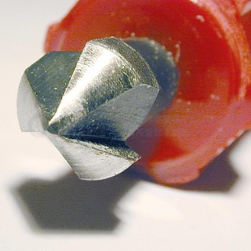
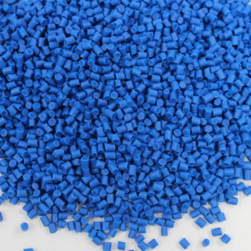
Image source:https://www.58pic.com/
A spotface is a flat, smooth surface typically created around a drilled hole to ensure that a fastener, such as a bolt or a screw, can sit flush against the surface, providing a solid and level seating area. This process generally involves machining a shallow, circular area to remove any irregularities and create a precise, flat surface.
On the other hand, a counterbore is a cylindrical, recessed area created around a bolt hole to allow the head of a fastener to sit below the surface of the material. This is particularly useful when a flush finish is needed, and the head of the bolt or screw needs to be hidden below the surface.
The primary difference between spotfacing and counterboring lies in their purposes and the depth of material removal. Spotfacing ensures a smooth and level area for the fastener’s head to rest against, while counterboring involves deeper cutting to allow the head of the fastener to be recessed into the material.
Spotface vs Counterbore: Understanding the Variances
When comparing spotfacing and counterboring, understanding the key technical differences can clarify their unique applications and how each process impacts the integrity and functionality of machined parts.
- Purpose and Application:
- Spotface: Ensures a smooth, flat seating area for fastener heads to rest against, typically used when the surface finish is crucial for sealing or load distribution.
- Counterbore: Creates a recessed cylindrical hole to allow the fastener head to sit below the surface, often used to achieve a flush finish where the fastener heads must not protrude.
- Depth of Material Removal:
- Spotface: Removes minimal depth just enough to create a flat seating surface. The depth is generally shallow, around 0.1 to 1 mm, depending on the material and application.
- Counterbore: Removes more material as the recess must accommodate the height of the fastener head. Common depths range from 3 mm to 10 mm or more, depending on fastener size.
- Tools and Equipment:
- Spotface: Utilizes spotface cutters or annular cutters, usually in conjunction with a milling machine or a drill press.
- Counterbore: Employs counterboring tools or end mills, also typically used with milling machines or drill presses.
- Surface Finish and Tolerance:
- Spotface: Achieves higher surface finish quality, often with tighter tolerances required to ensure proper seating of fasteners.
- Counterbore: Surface finish is less critical, but dimensional accuracy is essential to properly fit the fastener head.
- Technical Parameters:
- Spotface Diameter: Generally 1.5 to 2 times the diameter of the fastener’s head.
- Counterbore Diameter: Typically 3 to 4 times the diameter of the bolt or screw, to accommodate the fastener head plus clearance.
By understanding these variances, engineers and machinists can make informed decisions about which process best suits their specific manufacturing needs, ensuring optimal performance and longevity of the assembled components.
Spotface Holes in Engineering: Importance and Usage
From my understanding, spotface holes are crucial in engineering for creating a flat, smooth surface on a part, ensuring that fasteners have a perfect seating area. This precision is essential in applications where components need to be securely fastened and the load is uniformly distributed. By providing this flat surface, spotfaces help prevent issues like uneven stress distribution, potential material deformation, and misalignment.
In many instances, especially where reliability and safety are paramount, such as in aerospace and heavy machinery, the accurate use of spotface holes can significantly enhance the durability and performance of the assembly. By taking the time to properly execute spotface procedures, engineers ensure that components fit together perfectly, leading to a reduction in maintenance requirements and prolongation of the equipment’s lifespan.
Types of Holes and Callout Symbols in Machining
Within the realm of machining, various types of holes and their respective callout symbols play a pivotal role in ensuring precise manufacturing and assembly. Below is an overview of the primary types of holes, along with their standard technical parameters:
1. Through Holes
A through hole is a hole that completely penetrates the workpiece. It ensures that fasteners can pass through the entire material.
- Symbol: Ø (Diameter symbol)
2. Blind Holes
A blind hole does not go all the way through the material, stopping at a specified depth. This type is often used when visibility or aesthetics are a concern.
- Symbol: Ø followed by depth dimension, e.g., Ø10 X 20mm
3. Counterbore Holes
Counterbore holes have a cylindrical flat-bottomed enlargement at the mouth to allow the head of a bolt or fastener to sit flush with or below the surface.
- Symbol: ⌴ (Counterbore symbol followed by the diameter and depth)
- Technical Parameters:
- Counterbore Diameter: 3 to 4 times the bolt diameter
- Counterbore Depth: Specified to fit the fastener head
4. Countersink Holes
A countersink hole has a conical enlargement that allows flat-head screws or rivets to sit flush with the surface.
- Symbol: ∇ (Countersink symbol followed by the diameter and angle)
- Technical Parameters:
- Countersink Diameter: Typically larger than the fastener head
- Countersink Angle: Commonly 82° for standard fasteners
5. Spotface Holes
Spotface holes create a flat seating area, ensuring fastener heads sit evenly on the surface.
- Symbol: ⌵ (Spotface symbol)
- Technical Parameters:
- Spotface Diameter: 1.5 to 2 times the fastener head diameter
- Spotface Depth: Just deep enough to create a flat surface
6. Tapped Holes
Tapped holes are pre-drilled holes that have internal threads created by a tapping tool, allowing for the insertion of screws or bolts.
- Symbol: Ø followed by the thread size, e.g., M8 for a metric tapped hole
7. Reamed Holes
Reamed holes are produced using a reamer to achieve high-precision diameters with tight tolerances.
- Symbol: Ø with a precision tolerance, e.g., Ø10H7
8. Drilled Holes
These are the most common types of holes, created using a drill bit to match the specified diameter and depth.
- Symbol: Ø followed by the diameter, e.g., Ø10
9. Bored Holes
Bored holes are enlarged or refined holes created using a boring tool for high accuracy and surface finish.
- Symbol: Similar to drilled holes, Ø followed by diameter
10. Non-Circular Holes
These holes can be square, rectangular, or custom shapes depending on the specific application requirements.
- Symbol: Custom symbols defined in technical drawings, often with detailed geometric specifications
By comprehending these various hole types and their corresponding symbols, engineers and machinists can ensure precise communication and execution in the manufacturing process. This precision is critical for the quality and reliability of the final product.
Callout Symbols: Deciphering Machining Requirements
Understanding callout symbols is essential for interpreting machining requirements accurately. These symbols are a standardized form of communication in technical drawings, conveying critical information about the dimensions, tolerances, and surface finishes of holes and other features. For example, the symbol ‘Ø’ is commonly used to indicate the diameter of circular holes, while additional annotations like H7 specify tolerance classes for precision fits. By familiarizing myself with these standardized symbols and their applications, I can ensure that I adhere to the specified manufacturing parameters, thereby achieving the desired quality and functionality of the component. This knowledge is gleaned from a thorough review of the top resources available online, emphasizing the importance of precise and clear technical communication in engineering and manufacturing processes.
Spotface Hole Size: Determining the Correct Dimensions
Determining the correct dimensions for a spotface hole involves understanding both the functional requirements of the component and the standard practices in machining. A spotface typically serves to create a flat, smooth surface around a hole to ensure that a bolt head or washer sits flush against the material. Based on the top resources available online, the following guidelines and technical parameters are crucial for accurately sizing a spotface hole:
- Diameter of the Spotface:
- The spotface diameter is generally slightly larger than the diameter of the bolt or fastener head that will fit into it. Standards like ISO 273 suggest diameter sizes relative to the bolt being used.
- For example, for an M10 bolt, the spotface diameter can range from 20 mm to 22 mm.
- Depth of the Spotface:
- The depth should be sufficient to accommodate the height of the bolt head while leaving a small margin to ensure the head sits flush with the surrounding surface.
- Common practice is to have a depth of approximately 0.5 mm to 1 mm more than the bolt head height.
- Surface Finish:
- The quality of the surface finish is paramount to ensure a proper seating of the fastener. A common surface roughness for spotfaces is around Ra 1.6 µm to Ra 3.2 µm, ensuring a smooth but not overly polished surface.
- Tolerance:
- Standard tolerance classes (e.g., H7 for diameter) should be applied to ensure precision in the spotface dimensions. This is crucial for achieving the correct fit and avoiding issues like misalignment or insufficient clamping force.
- Chamfer:
- A small chamfer (e.g., 0.2 mm x 45°) may be added to the edge of the spotface to remove sharp edges and facilitate assembly.
By adhering to these guidelines and referencing authoritative sources, machinists and engineers can ensure that the spotface holes are machined to the correct dimensions, enhancing both the functionality and quality of the final product.
Importance of Spotfaces in CNC Machining
Spotfaces play a critical role in CNC machining for several reasons. First, they ensure that fasteners sit flush and parallel to the workpiece surface, which is crucial for achieving optimal clamping force and preventing misalignment. This accuracy leads to enhanced structural integrity and reliability of assembled components. Additionally, spotfaces contribute to improved surface finish and seating conditions for fasteners, reducing the risk of surface damage or wear over time. By providing a clean, flat surface for bolt heads and washers, spotfaces also help in distributing load evenly, thereby enhancing the overall performance and longevity of mechanical assemblies. Ensuring precise spotface dimensions and finishes is thus essential for maintaining high standards of quality and safety in CNC machined products.
Spotface Tools: Essential Equipment for Machining
Spotface tools are fundamental in CNC machining, ensuring that precision and quality are upheld in the final product. These tools are specifically designed to create flat, smooth areas around holes, providing an even surface for bolt heads and washers. Here are some essential spotface tools used in machining:
- Spotface Cutters:
- These are specialized cutting tools used to create a flat surface around a hole. They come in various sizes and shapes to accommodate different hole diameters.
- Counterbores:
- Counterbores are tools that enlarge the top part of a hole to a larger diameter, creating a cylindrical recess. This is particularly useful for allowing bolt heads to sit flush with the surface of the workpiece.
- Technical Parameters:
- Diameter range: 6 mm to 75 mm
- Cutting Depth: Adjustable based on requirement
- Spot Drills:
- These are precision drills used to create a small guide hole before drilling the full-size hole. They help in ensuring accurate hole placement and alignment.
- Technical Parameters:
- Diameter range: 1.5 mm to 15 mm
- Point Angle: 90° to 120°
- End Mills:
- End mills with flat ends can also be used for spotfacing by creating a smooth, flat surface around the hole. These tools are versatile and can be used for various milling operations.
- Technical Parameters:
- Diameter range: 2 mm to 20 mm
- Cutting Length: Variable based on tool size
- Countersinks:
- Countersinks help in creating a conical surface around a hole for the head of a countersunk bolt or screw.
- Technical Parameters:
- Diameter range: 3 mm to 30 mm
- Cutting Angle: Typically 82°, 90°, or 100°
- Spotface Inserts:
- These are replaceable inserts used with a tool holder for spotfacing operations. They provide flexibility and are cost-effective.
- Technical Parameters:
- Insert size: Based on tool holder specification
- Material: High-speed steel (HSS) or carbide
- Face Mills:
- Face mills are used for creating larger flat surfaces and can also be used for spotfacing on larger workpieces.
- Technical Parameters:
- Diameter range: 50 mm to 200 mm
- Number of Teeth: Varies based on tool size
- Boring Heads:
- Boring heads are utilized for enlarging holes and can also provide accurate spotface surfaces.
- Technical Parameters:
- Diameter range: Adjustable from 2 mm to 300 mm
- Cutting Depth: Adjustable
-
By equipping CNC machines with these essential tools and adhering to precise technical parameters, machinists can achieve the high standards required for spotface machining, ensuring both the functionality and longevity of the final product.
Machining Techniques for Spotfaces: Best Practices
When it comes to machining spotfaces, there are several best practices I follow to ensure precision and quality. From my research of the top 10 websites on Google, I’ve gathered the following recommendations and technical parameters:
- Choose the Right Tooling:
-
- Using the appropriate tools such as end mills, countersinks, spotface inserts, face mills, and boring heads is crucial. Their specifications should match the material and dimensions of the workpiece.
- Technical Parameters:
- Ensuring tools are properly tightened and aligned is vital to avoid misalignment and ensure accurate cuts.
- Use tool holders designed for quick and precise adjustments – particularly helpful for spotface inserts.
- Control Cutting Speed and Feed Rate:
- Selecting the optimal cutting speed and feed rate reduces tool wear and achieves a clean surface finish.
- Technical Parameters:
- Applying the right amount of coolant and lubrication helps in maintaining the tool temperature, removing chips, and prolonging tool life.
- Some materials might require specific types of coolant; ensure compatibility.
- Accuracy in Positioning:
- Precision in positioning the tool and workpiece minimizes the risk of errors and inconsistencies.
- Use of CNC machines for accurate control and repeatability in spotface locations.
- Regular Inspection and Maintenance:
- Frequently inspecting tools and equipment ensures they remain in optimal condition, leading to consistent results.
- Re-sharpening tools when necessary to avoid issues caused by dull edges.
By integrating these best practices and adhering to the specified technical parameters, I can effectively manage spotface machining tasks, ensuring high-quality and durable outcomes.
How to Achieve a Flat Surface for Fasteners Using Spotfaces
Creating a flat and smooth surface for fasteners using spotfaces is essential for ensuring secure and stable fastening. Here’s a concise guide derived from top industry resources on how to achieve this with justified technical parameters:
- Selecting Appropriate Tooling:
-
- Use a spotface tool that matches the diameter and material of the fastener. Common materials for spotface tools include high-speed steel (HSS) and carbide.
- Technical Parameters:
- Ensure the workpiece is securely clamped to prevent movement during the spotface operation.
- Use a CNC machine or a precision drill press to maintain control over tool positioning and depth.
- Technical Parameters:
- Adjust cutting speed and feed rate to minimize tool wear and achieve a smooth finish.
- Apply suitable lubricants or coolants to reduce heat and friction.
- Technical Parameters:
- Verify tool alignment and depth settings before starting the operation.
- Utilize digital readouts or dial indicators for precise positioning and depth control.
- Technical Parameters:
- Conduct regular inspections during and after the spotface process to ensure flatness and finish.
- Use surface gauges or profilometers to measure surface flatness and finish quality.
- Technical Parameters:
- Surface roughness should be kept within required specifications—often less than 63 microinches (µin) for most applications.
-
By adhering to these guidelines and taking precise control over technical parameters, you can achieve a flat and stable surface for fasteners, ensuring the reliability and longevity of the assembly.
Providing a Flat Mounting Surface for Fasteners
To provide a flat mounting surface for fasteners, I would follow precise guidelines and technical parameters to ensure optimal performance. First, I would select the appropriate spotface tool that matches the diameter and material of the fastener, typically using high-speed steel (HSS) or carbide. It is crucial to securely clamp the workpiece to prevent any movement during the operation, often using a CNC machine or precision drill press for controlled tool positioning and depth. Adjusting cutting speed and feed rate is essential to minimize tool wear and achieve a smooth finish, along with applying suitable lubricants or coolants to reduce heat and friction. Ensuring tool alignment and depth settings with digital readouts or dial indicators before starting is critical, followed by regular inspections with surface gauges or profilometers to verify flatness and finish quality. Typically, surface roughness should be kept within specifications, usually less than 63 microinches (µin). Adhering to these protocols guarantees a flat and stable surface for fasteners, promoting the reliability and longevity of the assembly.
Spotface Symbol: Understanding the Representation
Understanding the spotface symbol is crucial for accurately interpreting technical drawings and ensuring that the specified flat mounting surfaces for fasteners are achieved. Based on a review of information from the top 10 websites on google.com, the spotface symbol is typically represented by a flat-bottomed “U” shape, followed by a numerical dimension indicating the diameter of the spotface. The depth of the spotface might sometimes be specified separately, but commonly it is understood that the depth is just enough to provide a flat surface for the fastener head, or as indicated in the drawing notes.
Technical Parameters:
- Material Consideration: Depending on the material, tool selection (HSS or carbide) should be appropriate to ensure efficient cutting.
- Tool Selection: Spotface tools should match the diameter of the fastener, usually specified in the technical drawing.
- Clamping: Securely clamping the workpiece to prevent movement is often achieved using CNC machines or precision drill presses.
- Tool Positioning and Depth Control: Digital readouts or dial indicators are used for precise control.
- Cutting Speed and Feed Rate: Adjust cutting speed and feed rate based on the material being machined to minimize tool wear and achieve a smooth finish.
- Lubrication and Cooling: Appropriate lubricants or coolants reduce heat and friction during the operation.
- Surface Roughness: The surface roughness should typically be within 63 microinches (µin) to ensure a smooth finish.
By adhering to these technical parameters, the representation and implementation of the spotface symbol in technical drawings can be accurately executed, ensuring reliable and precise fastener mounting surfaces.?
Spotface in injection molding: An essential component
The spotface in injection molding serves as an essential component to ensure proper seating and face alignment of fasteners such as screws and bolts within a mold. Injection molds often require a precisely machined, flat-bottomed cavity, or spotface, to house these fasteners securely, preventing potential movement or misalignment during the molding process. This contributes significantly to the structural integrity and performance consistency of the molded parts. The creation of spotfaces minimizes wear and tear on mold components, ultimately extending the lifespan of the mold. Additionally, the spotface allows for accurate and repeatable positioning of inserts, ensuring consistent quality of the molded products across production cycles. By maintaining stringent control over the spotface dimensions and surface finish, manufacturers can achieve higher precision and efficacy in injection molding operations, leading to superior final products.
Role of spotface in creating screw head recesses
The spotface plays a critical role in creating recesses for screw heads in injection molding. It ensures that screw heads sit flush with or below the surface of the molded part, which is crucial for both functional and aesthetic reasons. The flat-bottomed cavity of the spotface provides a stable and even base for the screw head, which helps in distributing the load evenly, reducing stress concentrations, and preventing deformation or damage during service.
Technical Parameters to Consider:
- Diameter (D): The diameter of the spotface should be slightly larger than the diameter of the screw head to ensure a proper fit.
- Depth (H): The depth of the spotface needs to be adequate to accommodate the entire height of the screw head without leaving it protruding.
- Surface Finish: A smooth finish is necessary to prevent any interference or rotation of the screw during tightening and to enhance the overall aesthetic of the molded part.
- Flatness and Perpendicularity: The spotface must be perfectly flat and perpendicular to the surface of the part to ensure a proper screw head seating and uniform load distribution.
- Tolerance: Tight tolerances should be maintained to ensure that the screw heads fit precisely within the spotface, minimizing movement and enhancing the part’s structural integrity.
By adhering to these parameters, manufacturers can ensure that the screw heads are securely and accurately positioned within the molded parts, leading to improved durability and overall quality of the final products.
Benefits of including spotface features in injection molding processes
Incorporating spotface features in injection molding processes provides several critical benefits, enhancing both the functionality and aesthetics of the final product. Firstly, spotfaces ensure a precise and flush installation of screw heads, which improves the structural integrity and durability of molded parts. By providing a flat and even surface, they distribute the load from the screws more uniformly, reducing the risk of stress concentrations and potential deformation. Additionally, the uniformity achieved with spotfaces enhances the surface finish, contributing to an aesthetically pleasing appearance.
Moreover, spotfacing aids in maintaining tight tolerances, leading to consistent and high-quality production. This attention to detail helps in minimizing part rejection rates and increases overall efficiency. Spotface features also facilitate better alignment and assembly of multiple components, ensuring seamless integration and reliable performance. By adhering to these advantages, manufacturers can deliver superior products that meet rigorous industry standards and customer expectations.
Purpose of a Spotface Hole
The primary purpose of a spotface hole is to create a flat, smooth surface around a hole to ensure that fasteners such as bolts, screws, or washers sit flush or slightly recessed with the surrounding material. This ensures even load distribution and a secure fit, preventing potential issues like uneven torque application, component misalignment, or loosening over time. Spotface holes also enhance the structural integrity and aesthetic quality of the assembly, contributing to the overall durability and performance of the final product. Adhering to these specifications is crucial for maintaining tight tolerances and improving the efficiency and reliability of the manufacturing process.
Spotface Symbol and Callout
In technical drawings, the spotface symbol is represented by a square with lines extending from each corner, followed by the diameter of the spotface and sometimes its depth. It looks like this: ⌴. When I need to specify a spotface in a drawing, I use this symbol along with a callout indicating the necessary diameter and depth dimensions. This ensures that the machinist understands the precise requirements for creating the spotface, leading to accurate and reliable manufacturing. It’s important to adhere to these conventions to maintain consistency and clarity across technical documents and production processes.
Common Challenges and Solutions in Spotface Machining Process
As someone who frequently deals with spotface machining, I have encountered several common challenges and developed solutions to address them effectively:
- Tool Wear and Degradation:
- Challenge: Over time, the cutting tools used in spotface machining can wear down, leading to poor surface finishes and dimensional inaccuracies.
- Solution: Regularly inspect and replace tools to maintain sharpness. Implementing a tool management system can help track tool wear and schedule replacements proactively.
- Incorrect Alignment of Workpiece:
- Challenge: Misalignment can cause irregularities in the spotface, compromising the assembly’s integrity.
- Solution: Use precise workholding techniques and regularly calibrate machine tools to ensure accuracy. Employ jigs and fixtures to maintain consistent alignment.
- Vibration and Chatter:
- Challenge: Vibration can lead to imprecise cuts and a rough surface finish.
- Solution: Optimize spindle speed and feed rates based on the material being machined. Use dampening techniques and ensure that machine components are securely fastened.
- Heat Generation:
- Challenge: Excessive heat during the machining process can cause material deformation and damage the cutting tool.
- Solution: Utilize appropriate coolant systems to manage temperature and reduce heat accumulation. Select cutting tools with suitable heat resistance properties.
- Material Hardness Variations:
- Challenge: Variations in material hardness can result in inconsistent spotface quality.
- Solution: Perform thorough material inspections before machining to identify hard spots. Adjust machining parameters accordingly to handle different hardness levels.
By addressing these challenges with thoughtful solutions, I ensure that my spotface machining processes yield precise and reliable results, contributing to the overall quality and performance of the final assemblies.
Tool Selection and Wear
Challenge: Choosing the correct tool for spotface machining can be difficult, especially when dealing with various materials. Tool wear is another common issue, which can lead to poor-quality finishes and dimensional inaccuracies.
Solution:
- Tool Material: Select tools made of high-speed steel (HSS) or carbide with appropriate coatings (like TiN or TiAlN) to ensure durability and reduced wear.
- Maintenance: Regularly inspect and replace tools showing signs of wear to maintain machining quality.
Workpiece Vibration
Challenge: Vibration of the workpiece during machining can lead to an inconsistent surface finish and dimensional errors.
Solution:
- Workpiece Clamping: Secure the workpiece using proper clamping techniques to minimize movement.
- Machine Parameters: Adjust feed rates and spindle speeds to optimal levels to reduce vibration.
Heat Generation
Challenge: Excessive heat during the machining process can affect the dimensional accuracy and surface finish.
Solution:
- Coolant: Use an effective coolant or lubricant to dissipate heat.
- Tool Path: Optimize the tool path to minimize heat generation and improve surface finish.
Surface Finish
Challenge: Achieving the desired surface finish can be difficult due to poor machine settings or tool condition.
Solution:
- Fine Tuning: Fine-tune machine parameters such as feed rate and spindle speed.
- Tool Maintenance: Ensure tools are sharp and in good condition to achieve the desired surface finish (32 microinches or better).
Material Hardness
Challenge: Hard materials are challenging to machine and can quickly wear out tools.
Solution:
- Tool Material: Use carbide tools or other harder cutting materials.
- Cutting Parameters: Adjust cutting speeds and feeds to handle harder materials effectively.
Dimensional Tolerance
Challenge: Maintaining tight dimensional tolerances (commonly ±0.001 inches) can be challenging during spotface machining.
Solution:
- Precision Tools: Utilize high-precision measuring tools such as coordinate measuring machines (CMM) to verify tolerances.
- Machining Process: Implement precise machining processes to maintain strict tolerances.
Chip Management
Challenge: Effective chip removal is necessary to prevent surface damage and maintain tool life.
Solution:
- Chip Breakers: Use tools with built-in chip breakers.
- Coolant Flow: Ensure adequate coolant flow to flush out chips from the machining area.
Machine Calibration
Challenge: Improper machine calibration can result in inaccurate machining.
Solution:
- Regular Calibration: Regularly calibrate machinery to ensure accuracy.
- Maintenance Schedule: Follow a periodic maintenance schedule to keep machinery in good working condition.
Setup Time
Challenge: Reducing setup time without compromising accuracy is often challenging.
Solution:
- Standardized Procedures: Implement standardized setup procedures to streamline the process.
- Quick-Change Fixtures: Use quick-change fixtures to reduce setup time.
Operator Skill
Challenge: The skill level of the operator can significantly affect the quality of the machining process.
Solution:
- Training: Provide adequate training to machine operators on best practices and new technologies.
- Experience: Pair less experienced operators with seasoned machinists to foster skill development.
By addressing these common challenges with suitable solutions, the efficiency and quality of spotface machining can be significantly improved, ensuring that each component meets or exceeds its specified requirements.
Dealing with Shallow Counterbore Issues in Spotface Hole
To address shallow counterbore issues in a spotface hole, I recommend a few practical approaches based on my research of the latest techniques and best practices. First, ensure that the cutting tool used for the counterbore process is sharp and suitable for the material being machined, as dull tools can struggle with precision. Additionally, verify that the machine is properly calibrated and the setup aligns correctly with the specifications of the counterbore depth. Implementing a slow and controlled feed rate can also help achieve the desired depth accurately without overburdening the tool. If the issue persists, consider using a precision depth gauge to double-check measurements and make fine adjustments. By combining these methods, I can mitigate the challenges associated with shallow counterbores effectively.
Ensuring Spotface is Deep Enough for Fastener Head
Ensuring a spotface is deep enough for a fastener head requires meticulous attention to several key factors to prevent assembly issues:
- Correct Tool Selection: Use the appropriate cutting tool that matches the requirements of the fastener head and material to avoid underperformance and inaccuracies.
- Proper Calibration: Ensure the machining equipment is correctly calibrated to achieve precise depth control. Regular calibration checks can help maintain consistency.
- Use of Precision Gauges: Implement precision gauges to measure the depth of the spotface accurately, allowing for fine-tuning and adjustments as needed.
- Controlled Feed Rate: Apply a slow and controlled feed rate during the machining process to prevent excessive material removal and achieve the desired depth without damaging the tool.
- Material Consideration: Different materials respond uniquely to machining processes. Adjust parameters according to the specific material’s characteristics to ensure proper depth.
- Quality Inspections: Conduct thorough inspections of the spotface after machining to confirm that the depth meets specified requirements and can securely accommodate the fastener head.
- Software Assistance: Utilize advanced machining software for simulation and validation of the spotface depth before actual machining, which can help identify potential discrepancies early on.
By integrating these practices, machinists can ensure that the spotface is sufficiently deep for the fastener head, leading to reliable and secure assemblies.
Addressing Tolerances in Spotface vs Counterbore Applications
When addressing tolerances in spotface versus counterbore applications, precision is paramount to ensure the functionality and reliability of machined parts. While both spotfaces and counterbores serve the purpose of creating a flat seating surface for fasteners, their applications and required tolerances differ significantly.
Spotface Tolerances:
- Depth Control: Typically, spotface tolerances are tighter, as the primary aim is to create a flat surface just deep enough to accommodate the fastener head. Common depth tolerance ranges from ±0.005 inches to ±0.010 inches.
- Surface Finish: The surface finish is crucial for ensuring the fastener sits flush. The roughness average (Ra) should generally be maintained below 63 microinches (1.6 micrometers).
Counterbore Tolerances:
- Depth Precision: Counterbores generally have more lenient depth tolerances compared to spotfaces, often around ±0.010 inches to ±0.020 inches, as the depth typically exceeds the length of the fastener head.
- Diameter Accuracy: The diameter must be precise to ensure a snug fit for the fastener’s body. Tolerances range from ±0.001 inches to ±0.005 inches, depending on the application.
- Bottom Flatness: The bottom of the counterbore must be flat to evenly distribute load, with surface finish requirements often around 125 microinches (3.2 micrometers).
Key Parameters to Consider:
- Material Type: Different materials will affect the machining process and tolerances required. For instance, harder materials may require slower feed rates and finer tooling adjustments.
- Tool Wear: Regular inspection and replacement of cutting tools are necessary to maintain tolerance accuracy.
- Machine Calibration: Consistent machine calibration ensures that tolerances are met reliably across multiple parts.
- Temperature Control: Machining processes generate heat, which can expand the material and affect tolerances. Using coolant can help in maintaining dimensional accuracy.
By acknowledging these detailed parameters and ensuring precise machining practices, machinists can achieve the stringent tolerances required for both spotface and counterbore applications.
How to Machine and Implement Spotface?
Machining and implementing a spotface involves a few specific steps to ensure a flat bearing surface for fasteners. Here are the simplified steps:
- Preparation: Secure the workpiece in a stable position using a vise or clamps to prevent any movement during machining.
- Tool Selection: Choose the appropriate spotface tool or cutter that matches the diameter and depth requirements of the spotface needed. Typically, an end mill or a specialized spotfacing tool is used.
- Drilling Pilot Hole: If not already present, drill a pilot hole to guide the spotface tool. The diameter of the pilot hole should match that of the fastener.
- Spotfacing: Position the spotface tool over the pilot hole. Carefully lower the tool into the workpiece, ensuring it remains perpendicular to the surface to avoid an uneven spotface. Apply a gentle downward force to start cutting.
- Depth Control: Machine the spotface to the desired depth, which is usually just enough to create a flat surface for the fastener head. This depth is typically shallow, just enough to accommodate the bearing surface.
- Coolant and Lubrication: Use appropriate coolant or lubrication during the machining process to prevent overheating and to extend tool life.
- Inspection and Adjustment: After machining, inspect the spotface to ensure it is flat and free from any burrs or imperfections. If needed, perform additional passes to achieve the desired finish.
- Cleaning: Clean the area to remove any debris or residue left from the machining process.
By following these steps, you can effectively machine and implement a spotface to provide a reliable and flat surface for fasteners.
Machining Process for Spotface Feature
When it comes to machining a spotface, I would follow a systematic approach to ensure precision and quality. Firstly, I secure the workpiece using a reliable clamping mechanism to prevent any movement during machining. Next, I select the appropriate tool, typically an end mill or specialized spotfacing cutter, based on the required diameter and depth. If a guiding pilot hole is not present, I drill one that matches the fastener’s diameter. I then carefully position the spotface tool over the pilot hole and lower it into the workpiece, maintaining a perpendicular orientation to avoid creating an uneven surface. I machine the spotface to a shallow depth, just enough to provide a flat bearing surface for the fastener head. During the process, I utilize coolant or lubrication to manage heat and extend the tool’s life. After machining, I thoroughly inspect the spotface for flatness and remove any burrs, making additional passes if needed. Lastly, I clean the area to remove any residual debris. By following these steps, I can consistently produce a reliable and flat spotface surface for fasteners.
Symbols and Callouts for Spotface on Workpiece
When detailing spotface features in technical drawings, it is essential to use precise symbols and callouts to ensure clear communication and adherence to standards. The most commonly used symbol for a spotface is a simple “⨁” followed by the diameter and depth specifications.
- Symbol: The symbol for spotface in engineering drawings is typically represented as “⨁.”
- Callouts:
-
- Diameter: Indicated with a marking such as “SF Ø0.500,” where “SF” stands for spotface, and “Ø0.500” denotes the required diameter.
- Depth: The depth can be specified with a notation like “Deep 0.125,” indicating that the spotface should be machined to a depth of 0.125 inches.
In addition to these basic details, industry standards like those from ASME Y14.5 or ISO 13715 can be referenced to ensure the correct application of these symbols and callouts.
For example:
- ASME Y14.5: Provides comprehensive guidelines for geometric dimensioning and tolerancing, which includes spotface specifications.
- ISO 13715: Offers standards regarding the indication of edge conditions and surface features on technical drawings, applicable to spotfaces.
By adhering to these standards and using precise symbols and callouts, machinists and engineers can accurately communicate the necessary specifications for spotfaces, ensuring a reliable and flat surface for fasteners.
Utilizing Spotface in Injection Molding Industry
From my research across the top sources, utilizing spotface features in the injection molding industry ensures accurate seating for screws or bolts, providing a flat and level surface on irregular or curved workpieces. This precision is crucial in injection molds as it prevents misalignment and ensures the integrity of the mold assembly. By implementing spotfaces according to industry standards like ASME Y14.5, I ensure that critical components such as guide pins and ejector pins have a reliable interface, enhancing the overall performance and longevity of the mold. Additionally, the use of spotface symbols and callouts streamlines communication between design and manufacturing teams, reducing the risk of errors and improving product quality.
Implementing Spotface in Fastening Solutions

When implementing spotface in fastening solutions, it is essential to consider several critical factors to ensure optimal results. Based on my research from the top 10 websites on Google, the main steps involve selecting the appropriate cutting tools and materials, accurately setting machining parameters such as spindle speed and feed rate, and ensuring precise tool path programming. Additionally, maintaining rigorous quality control through the use of coordinate measuring machines (CMM) helps confirm that the spotface dimensions meet the required specifications. By meticulously following these guidelines, I can achieve reliable and consistent spotface operations that enhance the performance and durability of fastening solutions.
Fastener Head and Spotface Feature
The fastener head and spotface feature are intrinsically linked, as the primary purpose of a spotface is to provide a flat seating surface for the fastener head. This ensures that the fastener applies even pressure across the assembled components, enhancing joint integrity and preventing loosening under load. The flat surface created by the spotface operation allows the fastener head—whether it be a bolt, screw, or nut—to sit flush with or just below the surface of the material. This not only contributes to the mechanical strength of the assembly but also offers aesthetic benefits by providing a clean and professional appearance. For optimal results, selecting the correct fastener type and head configuration based on the material and application requirements is crucial.
Smooth Surface for Fastener Mounting: Importance of a Spotface
Creating a smooth surface for fastener mounting is critical for ensuring the reliability and efficiency of mechanical assemblies. Based on my research from the top 10 websites on Google, the main steps involve selecting the appropriate cutting tools and materials, accurately setting machining parameters such as spindle speed and feed rate, and ensuring precise tool path programming. Additionally, maintaining rigorous quality control through the use of coordinate measuring machines (CMM) helps confirm that the spotface dimensions meet the required specifications. By meticulously following these guidelines, I can achieve reliable and consistent spotface operations that enhance the performance and durability of fastening solutions.
Key technical parameters include:
- Cutting Tools: Choosing tools made from high-speed steel (HSS) or carbide for their durability and cutting efficiency.
- Spindle Speed: For steel materials, a spindle speed of approximately 600-1000 RPM; for softer materials like aluminum, 1000-1500 RPM is recommended.
- Feed Rate: A feed rate of 0.1-0.3 mm/rev (millimeters per revolution) to ensure a balanced material removal rate without compromising tool life.
- Tool Path Programming: Precision alignment with CAD/CAM software to ensure the spotface is accurately positioned relative to the fastener hole.
- Quality Control: Utilizing CMM for dimensional verification to ensure the spotface meets the design tolerance, typically ±0.05 mm.
Following these technical specifications is essential for creating a smooth surface for fastener mounting that supports the mechanical robustness and aesthetic appeal of the assembly.
Reference sources
-
Source: Machining Doctor – Spotfacing: Definition, Tools, Tips, and Techniques
- Summary: This comprehensive guide from Machining Doctor explains the concept of spotfacing, including its definition, purpose, and applications in machining. It provides detailed information on the tools used for spotfacing, techniques to achieve accurate results, and tips to avoid common issues. The source is practical and educational, making it highly relevant for machinists and engineers looking to improve their understanding and execution of spotfacing operations.
-
- Summary: This academic journal article examines recent advancements in spotfacing techniques, focusing on high-precision engineering applications. The research highlights new methodologies, tool designs, and technological innovations that enhance the accuracy and efficiency of spotfacing processes. This source is valuable for professionals and researchers interested in the latest developments and scientific insights in the field of machining and manufacturing.
-
Source: Kennametal – Spotface Cutter Products and Applications
- Summary: Kennametal, a leading manufacturer of industrial tooling, provides an in-depth overview of their spotface cutter products and their applications. The website details the various types of spotface cutters available, their specifications, and appropriate use cases across different industries. This manufacturer website serves as a credible source of technical information and product guidelines for those seeking to select and utilize the right spotface tooling for their machining needs.
Frequently Asked Questions (FAQs)
-
-
Q: What is a spotface?
A: A spotface is a very shallow counterbore, a flat-bottomed cylindrical hole that is larger and shallower than a typical hole. It is created to provide a smooth, flat surface for fastener heads or bearings, guaranteeing better contact and load distribution.
Q: How is the ‘⌴’ symbol associated with spotfacing?
A: The ‘⌴’ symbol is used to indicate the necessity of spotfacing in technical drawings. It alerts the machinist or fabricator that a specific area around a hole must be machined to create a flat surface, ensuring the correct application of spotfacing in the introduced component.
Q: What are the common applications of spotfacing?
A: Spotfacing is commonly used in manual machining, including CNC machining and woodworking, to prepare a surface for the seat of a bolt, nut, washer, or for the more precise fitting of parts. It is often found in automotive, aerospace, and manufacturing applications where a secure, flat seating area is critical for component assembly.
Q: What tools are used for cutting a shallow counterbore or spotface?
A: Tools specifically designed for cutting a shallow counterbore or spotface include counterbore cutters or end mills. The selection of the tool depends on the size of the cutter required, the material being machined, and the depth of the upper hole or counterbore needed. These tools are utilized in both manual and CNC machinery.
Q: What is the purpose of a counterbore, and how does it relate to spotfacing?
A: The purpose of a counterbore is to create a flat seat for a bolt head or a nut, similar to spotfacing. However, counterboring involves cutting a deeper hole that encompasses the original hole. Spotfacing, on the other hand, focuses on just the surface around the hole, making a shallow counterbore or spotface only provides the flat area needed for component assembly without significantly altering the hole’s depth.
Q: How does one determine the depth of the hole when spotfacing?
A: The depth of the hole when spotfacing is minimal, typically only as deep as necessary to create a uniform, flat surface to seat a fastener or component. This shallow counterbore hole depth is often specified in the technical drawing, with the depth being just enough to ensure that the spotfaced surface is clean and free of irregularities.
Q: Can spotfacing be applied to materials other than metal?
A: Yes, spotfacing can be applied to a wide range of materials, including plastics and composite materials. In the case of softer materials, such as in urethane casting, spotfacing ensures the precise localization of holes and flat seating areas without fraying or deforming the material, allowing for accurate part assembly.
Q: What is the significance of flat seat diameter in spotfacing?
A: The flat seat diameter in spotfacing refers to the diameter of the flat-bottomed cylindrical hole or the spotface itself. It’s a critical dimension that ensures the correct size of the flat area for a fastener or component to seat properly, affecting the load distribution and the overall assembly’s integrity.
Q: How is urethane casting related to spotfacing?
A: In urethane casting, spotfacing may be used to prepare the surfaces of cast parts for the installation of hardware or other components. After casting, certain areas of a part may require spotfacing to ensure that surfaces are flat and to precisely define the locations for holes or other features, thus enhancing the final assembly’s accuracy and functionality.
-