
What are the Key Differences between Solid Edge and SolidWorks?
Image source: https://medium.com/
User Interface
Solid Edge boasts a modern interface that uses tabs. It is easy to use and understand, especially if one has used Microsoft Office products before. On the other hand, Solidworks has an interface that relies on drop-down menus which makes it very similar to most Cad software therefore many people prefer it.
Functionality
SolidEdge is great when it comes to functionality because of its Synchronous Technology, which lets you combine direct modeling’s speed and simplicity with parametric design’s flexibility and control. What this means is that designers can make changes to their models fast. Another thing is that rapid iterations are supported during design process. However, while being popular for its simulation features such as these ones mentioned above in contrast SolidWorks has a wide range of tools for performing extensive analysis and testing of designs – under different conditions too- which is good for complex engineering projects.
Industry Applications
Although both programs are used across various industries, each one predominates in certain areas. For instance consumer goods or machines where there might be need for many design changes in short time span usually go with solid edge because they can do things quickly but accurately at the same time .On the other hand aerospace automotive medical devices sector always opts for solid works due to precision requirements besides detailed validation needed during manufacture process step by step .
Support Services
In cases requiring assistance, both softwares have online communities tutorials etcetera . Nonetheless,solidwork’s user base is larger than any other cad right now so you can find someone who knows how to fix your problem or someone who had similar issue 24/7 . Additionally it also has very high quality customer support service compared to competitor like them partner networks provide extensive training materials globally accessible through internet regardless where we are located geographically speaking around world.
Comparing Solid Edge and SolidWorks Interfaces
Solid Edge and SolidWorks both have user-friendly interfaces that are easy-to-use to the maximum. However, they have unique features that cater to different types of users.
A familiar ribbon-based interface is one of the good things about Solid Edge and so is this feature for other programs. This interface arranges commands on tabs in relation to what you are doing at each stage of design making them easier to find. Furthermore, Synchronous Technology in Solid edge allows simplicity in modeling directly with control on parameters thereby giving more freedoms.
Customizable command managers differentiate Solidworks from its counterpart by enabling users personalize their toolbar layout such that frequently used tools can be accessed easily without wasting time during workflow process. It also presents part and assembly features logically through a feature manager design tree which makes it easy to navigate through complex models when compared with other software packages available today. The strength of this application lies in its ability to provide an intuitive design experience coupled with powerful simulation integration within the interface itself among many others.
To sum up; if you prefer structured environments like ribbons or direct modeling capability then go for solid edge but if customizability matters most alongside seamless integration between analysis tools during designing phase go for solid works.
Using Synchronous Technology in Solid Edge versus Parametric Modeling in SolidWorks
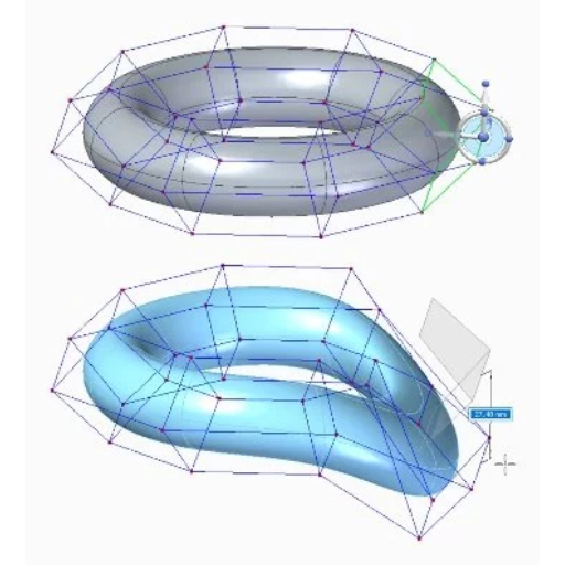
To compare Synchronous Technology in Solid Edge and Parametric Modeling in SolidWorks, it is important to understand how each method increases design efficiencies in different ways. In Solid Edge, Synchronous Technology is a hybrid of parametric and direct modeling; this means that designers can make models faster and edit them more quickly too as they are not tied down by traditional history-based design structures but rather allow for rapid iterations and intuitive modifications. It also supports real-time changes and multi-user collaboration by allowing features to be directly manipulated hence a great help in speeding up the process.
In contrast with this approach is the reliance on Parametric Modeling which is evident within SolidWorks itself where geometrical shapes are defined through series of parameters or constraints that control their behaviour predictably most times though not always so. This method works best when dealing with complicated relationships among objects contained within a model while ensuring accuracy since it gives engineers greater control over their designs; thus if one part changes other related features will automatically adjust accordingly thereby maintaining design intent throughout the entire system. The use of parameters allows for detailed documentation and consistency in projects done using SolidWorks during development stages because any alteration made affects every other component that depends on it.
Solid Edge featuring synchronous technology suits those who want fast flexibilities into designs without following orthodox methods while on the other hand solidworks parametric modeling provides structure along with predictability during complex assemblies or stringent requirements for designing purposes.
How do SolidWorks and Solid Edge Handle Assembly Modeling?
In assembly modeling, SolidWorks and Solid Edge meet different requirements with strong features.
Assembly modeling is dealt with in a highly detailed and structured way by SolidWorks. This allows users to create complex assemblies easily by using parametric relationships. Components can be mated and constrained in such a way that their motion and interaction behave as designed. It works well when making large assemblies where controlling the exactness of how parts interact or behave is very important; also it has tools for detecting interferences which are useful in ensuring that everything fits together correctly.
Solid Edge takes an alternative route towards assembly modelling through its Synchronous Technology which provides more flexibility during this process as compared to other systems available today. With synchronous technology, you can edit parts directly within assembly context without worrying about breaking parametric history tree branches. For design methodologies, solid edge supports both top down and bottom up assembly approaches making it versatile enough to support various design strategies. It is good at speedy changes of assemblies since direct modelling capability makes faster adjustments possible while working on them concurrently.
Thus to put it briefly; if you need detailed documentation control alongside precise manipulation of parts during design then go for solidworks whereas if what matters most is speediness combined with flexibility plus ability work together at once on different designs involving many components changing often between themselves – choose solid edge!
Which 3D CAD Software is More User-Friendly: SolidWorks or Solid Edge?
Learning Curve for Solid Edge and SolidWorks
While assessing the learning curves of Solid Edge and SolidWorks, it’s necessary to take into account such factors as resources, community support and software complexity inherent in each program. According to several sources, generally speaking, SolidWorks provides a wide range of documentation as well as video tutorials combined with a large active user community which is greatly helpful for beginners to understand what the software can do. Many users state that with its structured interface and plenty of online tutorials, SolidWorks offers an easy path of learning especially for those who have worked with other parametric modeling tools before.
On the other hand, when compared against traditional parametric modeling systems like those used in SolidWorks; solid edge particularly through synchronous technology may seem difficult at first for novices. However, after becoming conversant with direct modeling techniques employed by this program many individuals find it useful for quick design changes. This means that once one is proficient in making adjustments rapidly using direct modeling features of solid edge then they can perceive them advantageous towards streamlining their workflow more especially if they are experienced designers. Training materials provided by both packages are strong but finally people choose what suits them basing on personal requirements coupled with adaptability to various modelling approaches.
Usability and Workflow in SolidWorks vs Solid Edge
When talking about its user-friendliness and workability, SolidWorks always comes to mind. Even beginners in CAD can use it easily due to the interface’s intuitiveness which is a result of its consistent layout and logical tool sequence. It is an excellent software for parametric design; it has many tools for creating intricate assemblies and parts. The fact that many people are using it now means that there are enough materials or tutorials available for download so as to speed up designing processes and fixing problems.
On another note, what sets Solid Edge apart from other softwares is its flexibility through Synchronous Technology, where you can edit directly without going back through the history tree thus saving time used on design revision. This makes this method ideal especially when working on projects with frequent updates or changes required within specified periods of time although some people might find this technique difficult at first but once you get used to it then everything becomes easy.
In summary, SolidWorks usually supports detailed structured projects because of their usability while Solid Edge offers more general purpose fluidity because they allow rapid alterations needed in dynamic environments. Frequently either parametric or direct modelling approach will be chosen based on what is required by the project itself as well as the user’s skill set in relation to these methods.
Comparing SolidWorks Interface with Solid Edge’s User Interface
With respect to interfaces, SolidWorks has a reputation for its easy-to-use and intuitive environment which is familiar to conventional CAD software setups. It follows a consistent and logical approach that even beginners can easily work with. Toolbars, command options as well as properties are all within reach hence minimizing the need for navigating through complicated menus thereby streamlining the design process.
On the other hand, what makes Solid Edge unique from others is its user interface (UI) design that incorporates Synchronous Technology. This UI enables users to interact with models dynamically thus making it more useful when frequent fast changes are required. The UI offers an extensive range of customization options; therefore, individuals can tailor it according to their workflow thereby increasing productivity but this may be daunting at first.
Each of them is strong in its own way: while SolidWorks provides directness suitable for complex projects where you have to go step by step accordingly, Solid Edge gives flexibility through high customizability so much needed in quick iterative design environments. The decision on which interface one should go for largely depends on whether they prefer structured design process or adaptive dynamic approach – both being equally important factors in achieving successful designs.
What File Formats Do SolidWorks and Solid Edge Support?
SolidWorks and Solid Edge can read many different file extensions as input or write them as output because they are so widely used among designers and engineers.
Examples of CAD file formats supported by SolidWorks include .sldprt (parts), .sldasm (assemblies), and .slddrw (drawings). It is also capable of importing files saved in IGES, STEP, DXF, DWG, Parasolid, ACIS, STL, PDF or JPEG format among others while exporting may be done to any of these formats too.
Similarly with its native formats for parts (.par), assemblies (.asm) and drawings (.dft), Solid Edge supports a variety of common CAD packages like IGES, STEP, DXF, DWG, Parasolid or STL. In addition to OBJ models there are also options for PDF documents with multiple pages; besides this it can save images into JPEG/PNG format among other things.
List of Supported File Formats in SolidWorks
SolidWorks is compatible with a wide range of file formats which makes it possible to integrate seamlessly into different design workflows and collaborate with other CAD systems. Here is an exhaustive list of all the supported file formats along with their technical parameters:
- Part Files: .sldprt
- Assembly Files: .sldasm
- Drawing Files: .slddrw
- IGES: .igs, .iges – Standard for the Exchange of Product model data, highly compatible format for interoperability.
- STEP: .step, .stp – ISO 10303 standard, widely used for data exchange among different CAD systems.
- DXF: .dxf – Drawing Exchange Format, used for CAD data exchange.
- DWG: .dwg – Native format for AutoCAD, compatibility with numerous drafting applications.
- Parasolid: .x_t, .x_b – Geometric modeling kernel format, essential for 3D model exchange.
- ACIS: .sat, .sab – Standard-file format developed by Spatial Corporation, widely used in CAD applications.
- STL: .stl – Stereolithography, common for 3D printing and rapid prototyping.
- PDF: .pdf – Adobe Portable Document Format, useful for document sharing and viewing.
- Image Formats: .jpeg, .jpg, .png, .bmp, .tif, .tiff – These are utilized for incorporating texture maps, background images, or creating visual presentations.
File Format Compatibility in Solid Edge
Solid Edge is flexible and efficient CAD software that can work with many file formats to ease data exchange and collaboration with other design solutions. Here’s a detailed list of them:
- Part Files: .par
- Assembly Files: .asm
- Sheet Metal Files: .psm
- Draft Files: .dft
- IGES: .igs, .iges – Ensures interoperability with other CAD systems through standard exchange.
- STEP: .step, .stp – Used for sharing 3D data across different CAD platforms.
- DXF: .dxf – Facilitates the exchange of 2D drawings.
- DWG: .dwg – Compatible for AutoCAD users and widely accepted in design and drafting contexts.
- Parasolid: .x_t, .x_b – Enables seamless exchange of 3D geometry data.
- ACIS: .sat, .sab – Standard format for 3D model data used in multiple CAD applications.
- STL: .stl – Commonly used in 3D printing and rapid prototyping.
- PDF: .pdf – For sharing and viewing documents effortlessly.
- Image Formats: .jpeg, .jpg, .png, .bmp, .tif, .tiff – Useful for texture mapping, background images, visual presentations etc.
How to Convert CAD Files from SolidWorks to Solid Edge
To convert CAD files from SolidWorks to Solid Edge, one must perform a number of procedures that will guarantee the smooth transfer of data. Provided below is a brief manual to help you do this:
- Export from SolidWorks:
- Open your SolidWorks model.
- Navigate to `File` > `Save As`.
- Choose a neutral file format such as IGES (`.igs`), STEP (`.step`), or Parasolid (`.x_t`, `.x_b`). STEP or Parasolid formats are usually recommended for better compatibility and data retention.
- Click `Save` to export the file in the selected format.
- Import into Solid Edge:
- Open Solid Edge.
- Go to `File` > `Open`.
- Select the file format you exported from SolidWorks (e.g., IGES, STEP, or Parasolid).
- Locate and select the file you saved from SolidWorks.
- Click `Open` to import the file into Solid Edge.
- Observe the following instructions if any appear; This could involve setting units among other things that may be necessary for successful completion of importing process.
- Verification and Cleanup:
- After all of that go through the model once it’s in solid edge and make sure everything looks right with the geometry/features tab.
- Check dimensions, constraints, assemblies, etc. to ensure they align with what was originally intended (i.e., the original design intent).
- Perform any necessary adjustments or clean-ups needed to refine the imported model for further editing and use within Solid Edge.
How Do Solid Edge and SolidWorks Integrate with Other CAD Software?
Integration of SolidWorks with AutoCAD
Furthermore, detailed drawings and sketches may be exchanged easily using built-in tools in SolidWorks for importing or exporting DXF/DWG files. In this case, one can open AutoCAD DWG files directly in SolidWorks and use powerful sketching tools to modify or manipulate 2D data as desired. On the other hand, SolidWorks models may also be exported as DWG files so that they can continue being worked on within AutoCAD.
Also, using neutral file formats like STEP or IGES could facilitate smooth 3D data transfer between these two packages; such formats are widely known for their compatibility hence ensuring that integrity of 3d geometry remains intact during exchange process.
Therefore when these techniques are put into practice users will find it easy to integrate Solidworks with Autocad thus ensuring seamless flow of work while maintaining accuracy in dimensions throughout both platforms.
Using Solid Edge alongside NX and SAP
Combining Solid Edge with NX and SAP can simplify product development and management tasks through the use of complementary features. Solid Edge is known for its strong 3D CAD capabilities, which can be used alongside NX that has advanced simulation functions as well as the ability to handle complex designs. These models are exported out of Solid Edge using neutral file formats such as IGES or STEP so that they can easily be imported into NX where they will then undergo further scrutiny aimed at making them better.
Alternatively, when integrated with SAP which is an enterprise resource planning system; this enables organizations to optimize their workflows throughout the entire company. It also helps in scheduling, inventory control among other core business functions. Companies can link CAD data from both Solid Edge and NX with SAP so that projects may be tracked better while materials are managed more effectively thereby aligning all departments around current information.
All these systems combined provide organizations with a unified design environment where production processes are connected seamlessly to business management activities thus improving efficiency and reducing errors.
How to Import and Export Data in SolidWorks and Solid Edge
Importing Data into SolidWorks
- Open the Import Wizard: Launch SolidWorks and click on `File > Open`. Select the file format you want to import from the drop-down menu of file types (e.g., STEP, IGES)
- Select the File: Pick out a file for importing, then press ‘Open’. The Import Wizard will lead you through these steps.
- Adjust Import Settings: If necessary (for example, units or specific data to be included), customize these settings and click on OK when finished.
Exporting Data from SolidWorks
- Open the File: Load the SolidWorks model you need to export.
- Select Export Option: Go to `File > Save As`.
- Choose Export Format: In the ‘Save as type’ dropdown menu, choose the desired format (e.g., STEP, IGES, STL).
- Configure and Save: Adjust export settings if necessary and click ‘Save’.
Importing Data into Solid Edge
- Start the Import Process: Open Solid Edge and navigate to `File > Open`.
- Select File Type and File: Choose the type of file to import (e.g., STEP, IGES) from the dropdown menu and select the file.
- Complete the Import: Follow any prompts for settings or adjustments and press ‘OK’ to complete the import.
Exporting Data from Solid Edge
- Open Your Design: Open the file in Solid Edge that you wish to export.
- Initiate Export: Go to `File > Save As`.
- Choose Format: In the ‘Save as type’ dropdown, select the export file type (e.g., STEP, IGES, STL).
- Finalize Export: Adjust any settings required for export and click ‘Save’.
Why Should You Choose Solid Edge over SolidWorks?

Advantages of Synchronous Technology in Solid Edge
Exploring Unique Features of Solid Edge for Product Design
Case Studies: Companies Using Solid Edge Successfully
- Ural Diesel Motor Plant (UDMZ)
The Solid Edge download was undertaken by UDMZ, the leading manufacturer of diesel engines worldwide. They were able to cut design time significantly and become more accurate in their work because they learnt a lot from this advanced capability and also it made possible faster building of prototypes coupled with efficient production process. In addition to that another thing which contributed towards improving output in terms of engineering at UDMZ is how easy was data synchronization when using this software; therefore designers could collaborate more easily.
- JCB
Solid Edge helped JCB, an international construction equipment manufacturer, to make its product development processes more effective. The use of Convergent Modeling and Generative Design features in Solid Edge enabled JCB to speed up design workflows and create machines with better performance that are also complex in nature. The other good thing about it is that robustnesss in managing data by this particular software package ensured smooth integration into large-scale operations within such types like those carried out by company worldwide thereby making sure teams can handle project files effectively while maintaining standards required for design quality.
- Swiss-based Engineering Firm – Güdel
What are the Benefits of Choosing SolidWorks over Solid Edge?

Why SolidWorks is Preferred for Mechanical Engineering
Moreover, it provides excellent support in creating detailed drawings and documentation necessary for manufacturing assembly. Furthermore, there is a strong community around this program with plenty of online resources available for troubleshooting or learning purposes; it also seamlessly integrates with other software packages like CAD or PLM tools thus fostering collaboration among different stakeholders involved in project execution while enhancing overall efficiency throughout various stages of project development life cycle (PDLC)
Advantages for Surface Modeling in SolidWorks
SolidWorks is supreme with surface modeling because of its wide range of strong tools and features that can be used to generate very intricate and sleek surfaces accurately. One of the major benefits is the fact that it has a user-friendly interface which makes it easy for engineers to navigate through and apply advanced surface modeling techniques. Different methods for creating surfaces are supported by the software like loft, sweep or boundary surfaces hence designers can effortlessly get their desired geometry.
Also, among other things in design works flows solid modeling tools are one of SolidWorks’ surface modeling capacities that may be applied without causing any inconveniences when dealing with complex or detailed models. This means imported geometries can be worked on using Surface Offset, Split or Trim Surface which are powerful features not forgetting about flexibility brought by this capability coupled with checking for errors during creation process as well ensuring high quality standards while repairing them so that overall design process improvement is achieved.
Besides; comprehensive visualization together with rendering tools offered by SolidWorks plays a significant role in enabling designers share their thoughts more effectively through realistic representations of modeled surfaces. Therefore these combined strengths have made it become most preferred software for many engineers and designers who want to come up with intricate high-quality surface models.
Feature-Rich Environment for Designing with SolidWorks
SolidWorks is a software that supports design and engineering. It has many features for any type of design or engineering task you may need to perform.
This program offers advanced 3D CAD capabilities which help in creating detailed and accurate 3D models. It enables one to modify their designs easily through the use of parametric design at any stage during the lifecycle of the design. The software also comes with simulation tools that can be used to predict how products would perform under different conditions in real life thus reducing on time taken as well as cost incurred when making physical prototypes.
Collaborative working has been made possible by cloud based services like 3DExperience where files can be shared among team members who are working on same projects even if they are not located within same geographical area. Real time collaboration is facilitated through this service too which means designers can work together at once no matter where they may be found geographically speaking Design checker is another feature provided by SolidWorks; this tool ensures that all designs meet specified standards thereby maintaining high quality throughout.
SolidWorks Electrical and SolidWorks PCB allow integration between electrical and printed circuit board (PCB) designs within one environment hence ensuring smooth running of different stages involved in designing such systems. Many file formats are supported by this software so there won’t be any compatibility issues when exchanging data between other CAD tools or systems.
How Do Solid Edge and SolidWorks Support Simulation and Analysis?
Strong simulation and analysis tools are offered by both Solid Edge and SolidWorks, which helps in the process of design and engineering. For instance, it is possible to carry out finite element analysis (FEA) in Solid Edge using its integrated simulation capabilities hence assisting one to evaluate stress, strain as well as thermal performance under different conditions of components. Additionally, this suite also features motion analysis functionalities together with fluid dynamics that enables full mechanical systems testing within solid edge.
Similarly though with more breadth when compared against its counterpart; Solidworks provides a wide range of simulations such as FEA ,thermal analysis among others like fluid flow simulations too . The major benefit associated with this wide range is its integration into CAD environment making possible quick tests through real-time simulation while designing products iteratively. Fatigue Analysis, vibration analysis or even optimization techniques can be done using solid works since they have advanced features which give detailed examination about the performance level for any given item.
In conclusion both software reduce physical prototyping greatly thus optimizing designs early during development stage leading to increased reliability and performance through virtual testing and comprehensive product analysis.
Capabilities for Finite Element Analysis (FEA) in SolidWorks
Simulation Tools Available in Solid Edge
Solid Edge features a vast array of simulation tools that have been developed for different types of engineering. Solid Edge Simulation is the core package, and it is able to embed very strong finite element analysis (FEA) capabilities directly into the CAD environment. Thus, one can study structural, thermal or vibration performance of components under real-world conditions. Specifically, this software supports linear static; normal modes as well as buckling analyses thereby making it suitable for assessing product durability comprehensively.
Another type of simulation tool in Solid Edge is Flow Simulation which allows users to determine how fluids move around their designs while also analyzing thermal aspects associated with such movement. This capability becomes very useful when optimizing heat management within systems especially those used in automotive or aerospace industries where good fluid dynamics are critical. Motion Simulation on the other hand helps evaluate mechanism performance by considering forces acting upon them together with velocities plus accelerations thus ensuring smooth interaction between different parts that are supposed to move relative to each other.
Additionally, the suite includes fatigue as well as durability testing modules designed for predicting lifespan of products subjected to cyclic loading thus enabling designers make better decisions at an early stage during development process. Therefore, these tools provide engineers with a seamless workflow thanks to their intuitive interfaces coupled with CAD integration resulting into optimized and reliable designs
Performance Comparison of SolidWorks and Solid Edge Simulations
Comparisons made between SolidWorks and SolidEdge in terms of simulation capabilities present numerous differences. However, solidworks simulation has been known for its strong analysis tools that include FEA for structural, thermal and fluid dynamics among others with a user interface which is easy to use by making complex simulations simple enough. In addition it seamlessly integrates into the wider system of solid works thereby providing dynamic and static analysis tools as well fatigue simulation that are necessary for iterative design processes.
However, on another hand, solid edge simulation holds its own ground with powerful CAD-embedded simulation tools. Besides this strength it also does well when it comes to giving immediate feedbacks about designs’ performance under different situations such as structures, temperatures or fluids among others. Additionally being integrated within CAD environment ensures smoothness in workflow thus reducing time spent moving from one software to another for design and simulation purposes.
The two platforms allow users perform advanced motion analysis where assemblies’ kinematics as well dynamics can be studied but usually solid works boasts of large user community as well wide range industrial applications while solid edge’s ease of use and directness to CAD interface during simulating process make it more suitable for rapid prototyping or iteration therefore depending specific needs or workflow preferences either may be chosen for tasks involving simulations by engineering team members ultimately.
Reference sources
-
Xometry – Solid Edge® vs. Solidworks®: Software Comparison
- Xometry offers a comprehensive comparison between Solid Edge and SolidWorks, focusing on the features and tools of each software. It highlights the primary focus areas and differentiators, helping readers understand which software might be more suited to their specific needs.
- Source: Xometry
-
Fictiv – Solid Edge® vs Solidworks® Comparison
- Fictiv provides an in-depth analysis of Solid Edge and SolidWorks, examining the differences in design approaches, including parametric and synchronous modeling. This resource is valuable for those looking to make an informed decision based on detailed technical specifications.
- Source: Fictiv
-
Engineering.com – SOLIDWORKS or Solid Edge?
- Engineering.com discusses the strengths and weaknesses of both CAD software options, offering insights into their simulation capabilities, user interface, and overall performance. This article is tailored to help professionals choose the right tool based on their specific requirements and industry standards.
- Source: Engineering.com
Frequently Asked Questions (FAQs)
Q: What are the primary differences between Solid Edge vs SolidWorks?
A: When comparing Solid Edge vs SolidWorks, the primary differences lie in user interface, parametric modeling abilities, and specific design tools. Solid Edge uses synchronous technology, which can offer more efficient direct modeling. On the other hand, SolidWorks is known for its robust parametric and feature-based approach.
Q: Which is more cost-effective: Solid Edge or SolidWorks?
A: The cost can vary depending on the reseller and the specific packages purchased. Typically, Solid Edge and SolidWorks have different pricing models and it’s best to compare based on your specific needs, such as required modules and add-ons for simulation, CAM, or advanced 3D modeling.
Q: How do the 3D modeling capabilities of Solid Edge compare to SolidWorks?
A: Solid Edge provides strong 3D modeling tools with its synchronous technology, allowing for easy edits and iterations. Compared to SolidWorks, which offers extensive features for creating detailed models and assemblies, the choice may come down to user preference and specific workflow requirements.
Q: Is SolidWorks easier to learn than Solid Edge?
A: This can vary depending on personal preference and previous experience with CAD design software. SolidWorks is known for its user-friendly interface, which may make it easier for beginners to learn. Solid Edge, with its synchronous technology, can have a steeper learning curve but offers powerful design capabilities once mastered.
Q: Can Solid Edge and SolidWorks integrate with other CAD software like Creo or Autodesk Inventor?
A: Yes, both Solid Edge and SolidWorks can integrate with other popular CAD programs. They support various file formats, enabling users to import and export models between different software solutions such as Creo, CATIA, and Autodesk Inventor.
Q: What kind of support and resources are available for Solid Edge and SolidWorks users?
A: Both Solid Edge and SolidWorks have extensive support networks, including online forums, tutorials, and user communities. It might be easier to find help for SolidWorks due to its larger user base. However, Solid Edge users also have access to resources provided by Siemens PLM Software and various reseller support services.
Q: Which CAD software is better for specific applications like injection molding or CAM?
A: Both Solid Edge and SolidWorks can be used for applications like injection molding and CAM, but the choice may depend on the specific toolsets and add-ons available for each software. SolidWorks is known for its comprehensive suite of tools geared towards these applications, while Solid Edge offers similar capabilities with the advantage of synchronous technology for quick edits.
Q: Do Solid Edge and SolidWorks use the same modeling kernel?
A: Yes, both Solid Edge and SolidWorks utilize the Parasolid modeling kernel for geometry creation and manipulation, which provides robust and reliable modeling capabilities.
Q: Are there any notable companies or industries that predominantly use Solid Edge or SolidWorks?
A: Both CAD solutions are used widely across various industries. SolidWorks is one of the most popular CAD packages, favored in industries such as automotive, aerospace, and consumer products. Solid Edge is also used by numerous companies, benefiting those who prefer synchronous technology for complex machine and equipment design.
Q: How do Solid Edge and SolidWorks handle collaborative design and file management?
A: Both CAD programs offer tools designed to assist in collaborative design and file management. Solid Edge provides built-in data management capabilities, which can be more integrated with Siemens PLM Software solutions. SolidWorks utilizes PDM (Product Data Management) systems that are highly recognized and widely used, making collaboration smooth and efficient.