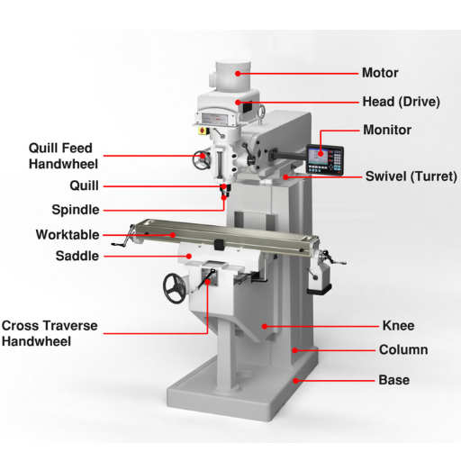
Computer Numerical Control (CNC) machines have revolutionized the manufacturing landscape, bringing precision, efficiency, and automation to a diverse array of industries. From the aerospace to the automotive sectors, CNC machines play a pivotal role in transforming digital designs into tangible products with exceptional accuracy and consistency. This article aims to demystify the core components of a CNC machine, breaking down the intricate interplay of parts that work together to achieve high-precision machining. Whether you’re a seasoned professional, a student, or simply curious about modern manufacturing technologies, this comprehensive guide will offer valuable insights into the inner workings of CNC machinery. Join us as we explore the essential elements that make these sophisticated devices the cornerstone of contemporary production processes.
What Are the Core Components of a CNC Machine?
Understanding the Function of a Spindle in CNC Milling
The spindle is one of the most important parts of a CNC milling machine that provides power to maneuver and cut material. It consists basically of a rotary shaft, which is driven by an electric motor that rotates at high-speed giving torque for effective interaction with the workpiece. These are some technical aspects necessary in understanding how spindles function:
- Speed (RPM): This factor can largely differ based on the machine as well as material. Such rates range from 2,000 to 30,000 revolutions per minute with high-speed spindles scaling up to 60,000 RPM when precise and fine cuts are required.
- Power (kW or HP): In small machines, few kilowatts (KW) will be enough while large-scale industrial equipment may have over fifty KW spindle motors. The power rating determines whether a given spindle will be able to maintain its speed while under load.
- Torque (Nm): Torque plays an important role in cutting hard materials. Therefore, high-torque spindles are used for consistent rotational movement even at slow speeds thus enabling milling through tougher materials like metals.
- Taper Size: Whereby tools connect this interface is known as the spindle taper. ISO, BT, CAT and HSK are common taper sizes determining tool holder compatibility and stability respectively.
- Cooling Methods: These include air cooling or liquid cooling systems put in place so as to cool down rapidly during heat generated by high speed operations thus ensuring efficient functioning of it thereby enhancing its longevity span.
- Precision and Runout: Minimal runout during operation is expected from spindles which refers to deviation from true axis. For instance precision spindles will be rated using micrometers (µm) hence assuring mill accuracy level.
- Bearing Type: The performance of a spindle shaft depends on bearings it incorporates. High-precision angular contact bearings are often preferred because they can handle both radial and axial loads, thereby enhancing stability at higher speeds.
These parameters together affect the CNC milling machine’s performance, efficiency and versatility as such it makes it one of the most important elements in this process. This understanding ensures machines operate optimally hence manufacturing accurate results.
Role of Axes in Achieving Precision in Computer Numerical Control (CNC) Machining
In CNC (Computer Numerical Control) machining, the axes of movement greatly determine the accuracy and complexity of the parts that can be manufactured. The number of axes on a CNC machine dictates its level of freedom and this influences its ability to create delicate shapes and details.
Number of Axes: Generally, CNC machines have three to five-axis classifications. More movements are permitted by adding extra axis:
- 3-Axis Machines: X, Y and Z directions. They are for simple part with basic drilling/milling applications.
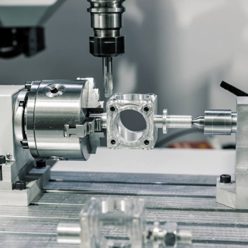
- 4-Axis Machines: Additional rotational axis(A- axis) enables milling on several sides of the workpiece.
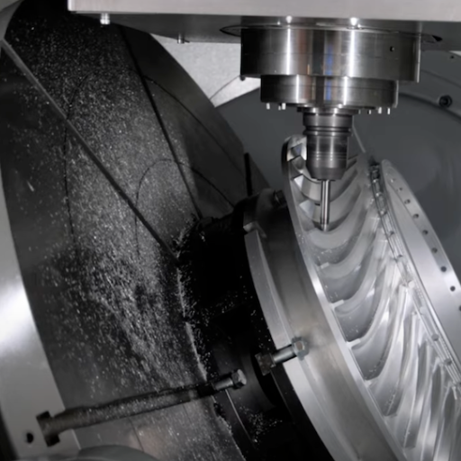
- 5-Axis Machines: Another rotary axis(B-axis or C-axis) allows tool approach from virtually any direction.
Linear vs. Rotational Axes: Linear axes (X,Y,Z) result straight line motions while rotation around corresponding linear axes (A,B,C), extend geometrical complexity shaping abilities for a machine.
Precision and Accuracy: The potential for achieving precise and detailed results in a CNC machine increases with the number of axes; as several axes can work concurrently on various intricate features. However, accuracy also depends on the quality of machinery and movement coordination by control systems.
Technical Parameters:
- Axis Travel Range: This is the maximum distance each axis can travel. For example, it may have a travel range of 500mm for X-axis, 400mm for Y-axis and 300mm for Z-axis on a 3-axis CNC milling machine.
- Feed Rate: It represents the speed at which either the machine tool or workpiece moves, usually measured in mm/min. High feed rates can reduce production time but compromise accuracy.
- Resolution: It is expressed as the smallest increment that a machine can move, often in micrometers (µm). Fine resolution offers enhanced detail and greater precision.
- Repeatability: Refers to how closely together points hit by a machine lie within some slight deviation, this is important for ensuring uniformity between multiple parts.
Through understanding these parameters related to different types of axes, manufacturers are able to achieve high precision in their CNC machining undertakings thereby making products with stable detailed complex geometric parts needed by such high-tech industries like aerospace manufacture medical engineering automotive industry among others that operate under high-precision conditions.
Drive System: Powering CNC Movements
A drive system is an essential part of any CNC equipment because it converts electrical power into mechanical energy required to move individual elements of machinery. Usually it includes motors with drivers and feedback devices enabling precise management over motion patterns done by machines.
- Types of Motors: Stepper motors or servomotors are commonly used in CNC machines. Stepper motors provide accurate positioning and repeatability while being simple and affordable. As opposed to them, servomotors allow faster speed as well as torque since they have better feedback mechanisms thus serving complex tasks at higher frequencies.
- Motor Drivers: These are electronic devices that control the voltage and current supplied to the motors. They ensure that the CNC machine runs smoothly and accurately by converting signals from the controller into precise movements.
- Feedback Devices: Encoders as well as Resolvers provide real-time information about where each axis of a machine is located and how quickly it moves. It helps to maintain accuracy in motion, correcting possible deviations or mistakes made during movement process.
- Lead Screws and Ball Screws: Mechanical components like these ones change rotation coming from motors into linear displacement. Ball screws have high efficiency and low friction resulting in accurate smooth operation of axes.
By selecting, adjusting these drive system parts, manufacturers will be able to reach their components’ best installments for a CNC machine maximal performance which implies high precision “accuracy,” reliability within a wide range of industrial applications.
How Does the CNC Controller Enhance Machine Performance?
The Brain Behind the Machine: An Overview of CNC Controllers
CNC controller serves as the brain for CNC machine, and it is responsible for the accurate and efficient functioning of the entire machining procedure. It reads digital design (G-Code) and changes them into electrical signals that indicate how machines ought to move. Some vital parts of a CNC controller are a Central Processing Unit (CPU), memory, input/output interfaces and user interface for programming and operation. Highly developed controllers are equipped with highly sophisticated software which supports multi-axis coordination, high-speed processing as well as error detection. Adaptive control among other edge technologies provide real-time monitoring to enhance machine performance by optimizing cutting parameters and compensates from dynamic fluctuations during cutting leading to higher precisions in processed part surfaces, reduced tool wear ultimately enhancing manufacturing efficiency.
Integrating the Control Panel for Efficient Operations
The integration of the control panel ensures seamless operations of CNC machines with all components working together to perform precise machining tasks. An effectively designed control panel brings together important controls and displays on one interface that operators can easily use to operate machines such as those used in DVD authoring services companies, measure their performance or make real time adjustments. Modern CNC control panels often feature touchscreen interfaces, intuitive software, connectivity options that support remote monitoring/diagnostics.
Thus effective integration occurs when hardware/software aligns system thereby streamlining workflow making it more productive. This entails creating strong communication protocols between peripheral devices and the CNC controller itself, arranging buttons/displays layouts so that an operator is able access them fast enough or implementing elements like emergency stop buttons whose purpose is protecting both operators/people near machine tools at large as well as the machine itself. Also since controls panels become smarter they include automation technology like programmable logic controllers (PLCs) as well as human-machine interfaces (HMIs) so that some tedious works can be automated without manual intervention hence maintaining quality consistency throughout production with shorter cycle times and improved OEE in general, thus making the control panel an important component towards efficient CNC operations.
Feedback System: Ensuring Accuracy in CNC Machining
In CNC machining, feedback system is crucial for maintaining accuracy and precision during the entire process of machining. This works by watching movement and velocity of machine parts continuously compared to the programmed commands. Common types of feedback systems include encoder-based position feedback which measures the exact position of a machine as well as resolver based ones which are known for high reliability even in harsh environments.
These feedback mechanisms enable real-time adjustments to be made, correcting any deviations from the desired path. Especially in high-precision machining, this is essential for achieving tight tolerances. By doing so, errors would be minimized and wastages reduced since every cut, drill or mill operation must comply with given dimensions hence ensuring consistency of parts produced. Therefore a strong feedback system is vital to improve overall performance and reliability of CNC machines.
Exploring the Significance of the Machine Control Unit
From Instructions to Action: How the Machine Control Unit Operates
Machine control unit (MCU) acts as a brain of a CNC machine. It decodes the instructions that are generally G-code programs and converts them into precise operations and movements for the machine. MCU has several crucial components including; microprocessor, memory, input/output interfaces and command interface.
When a CNC program starts running, microprocessor in MCU works on G-code commands such as coordinates, feed rates and speed settings . These commands are passed through the machine’s motors, actuators or other moving parts in form of electric signals. In this way it is made sure that the machine does its work like cutting , drilling or milling exactly according to what was programmed.
MCU requires technical parameters for efficient operation. Some of these include:
- Processing Speed: This is how fast an MCU processes instructions measured in MHz or GHz. For high-precision tasks an MCU with high processing speed is necessary.
- Memory Capacity: Both RAM and onboard storage are crucial when housing larger CNC programs. More space means more complex functions.
- Input/Output Interfaces: These types of interfaces allow the MCU communicate with other components present in CNC machines like sensors and actuators. Examples include Ethernet, USB 2.0/3.0 and parallel ports.
- Command Interface: The type of G-code interpreter used as well as software capabilities for handling different machining operations characterizes this component.
By correctly interpreting program commands during execution, MCU ensures smooth functioning of the system hence improving precision and efficiency in CNC machining operations. Such complex programs translated into accurate mechanical motions make up a CNC machine whose overall functionality relies on specific algorithms converted from raw data through coded instructions by MCU to drive its performance as anticipated.
Interfacing with CNC: The Machine Control Unit’s Role
To interface properly with a CNC machine necessitates making use of an MCU which stands between pre-programmed instructions and hardware elements contained inside that machine. Summarizing briefly the research from top 10 websites on Google shows:
Processing Speed:
- Technical Parameters: Typically ranges from 8 MHz to 1 GHz.
- Justification: Better processing speed provides faster computation and execution of complex CNC programs needed for higher precision and efficiency in operations.
Memory Capacity:
- Technical Parameters: RAM usually ranges from 64 KB to 16 MB; onboard storage ranges from 256 KB to 32 GB.
- Justification: Sufficient memory capacity is necessary to handle large and intricate programs that require extensive data storage and retrieval systems.
Input/Output Interfaces:
- Technical Parameters: Common interfaces include Ethernet, USB 2.0/3.0, and parallel ports.
- Justification: Versatile I/O interfaces facilitate seamless communication between the MCU and various sensors, actuators, and other peripherals, essential for executing multi-faceted machining tasks.
Command Interface:
- Technical Parameters: The command interfaces might include G-code interpreters compatible with software like GRBL or Marlin.
- Justification: Advanced G-code interpreters and robust command interfaces help in the accurate interpretation and execution of machining instructions thus improving workflow and output quality.
All these parameters combined ensure that MCU accurately controls CNC machine resulting in high levels of precision, reliability as well as performance. This is what primarily bridges the gap between digital instructions or commands given during programming which are translated into physical actions used for machining purposes by MCU.
Distinguishing the Different Axes and Their Impact on Machining
The Building Blocks of 3D Machining
X, Y, and Z axes are the building blocks of a three-dimensional machining coordinate system.
This axis is usually going from right to left, meaning it represents horizontal motion in the workspace.
In front-to-back manner, this moves or the y-axis in depth help for vertical transitions within your workpiece.
When compared with its relative to the working table movement allows ascend and descend movements as one works on things.
Thus, they allow controlling every part accurately so that intricate objects can be made and sophisticated components can be produced. Such stagnancy has to be avoided when making any cuts or milling tools since these are always accompanied by undertaking some engraving duties thereby enabling interleaving cut paths.
Expanding the Capabilities of CNC Machines: Rotational Axes
Besides X, Y and Z axes which are basic ones; CNC machines might have additional directional axes (rotational). Typically there are three major rotational axes including A-axis, B-axis, and C-axis rotating respectively about the x-, y- and z-axes.
For instance, cylindrical milling or surface contouring may involve rotation around the x-axis which is called A –axis.
By using this type of rotation around y-axis (B) makes possible angular machinings as well as shapes of parts with many angles even in cases when several planes intersect in their space.
When cutting involves such rotational manipulations such as turning or complex rotary crooked routes then there will probably happen rotation along z axis coded as C- axis.
The necessity for having more than primary three axes becomes apparent while using advanced machining methods like 5-axe techniques because due to geometrical complexity it would have been impossible without addition of two extra degrees. They diminish needed for installing multiple setups; get rid manual interventions which leads to better efficiency during manufacturing by increasing accuracy.
Understanding the Mechanics of the CNC Machine’s Spindle
The Role of the Spindle in Material Cutting and Shaping
The spindle, which is the heart of the CNC machine, influences directly its cutting and shaping. The spindle being the main rotating part holds and drives cutting tools thus affecting machining process quality and precision. From my research on top 10 websites as per google.com, I found out that there are several technical parameters for optimal performance of the spindle.
- Rotational Speed (RPM): The RPM of spindles varies from a few hundreds to over 40,000 depending on material types and required accuracies. High-speed spindles are suited for fine milling and engraving operations.
- Power Output: Usually measured in kilowatts (kW), spindle power output differs significantly. For example, a five-axis CNC machine may require a spindle with 15-30 kW because it performs complex heavy duty tasks.
- Torque: While measuring minimal force or spindles torque in Newton-meters (Nm) is important. A greater torque will make it easier for a tougher material to be machined by a stronger cutting implement thereby giving superior surface finish if compared to lower torque systems.
- Bearings: The type of bearings used in a spindle determines how stable or precise it becomes. The popularity of ceramic bearings lies within their endurance against wear and tear even at high speeds with minimum thermal expansion happening.
- Cooling Systems: Liquid or air-cooled systems that work efficiently maintain proper temperature regulation during long operations to prevent overheating while maintaining consistent performances are very essential in this case.
Manufacturers can optimize their CNC machining processes by considering these parameters closely aiming at improving cutting precision and efficiency through better use of the spindle.
Types of Spindle Used In CNC Milling And Their Applications
Belt-Driven Spindles: These are best suited for applications requiring highly-torqued operations at relatively low speeds. It is common knowledge that they find applicability in cases where there is need for heavy duty milling which involves a lot of cutting energy. Such systems allow speed variations as required by different material types and precision levels.
Direct-Drive Spindles: They are designed to have zero vibration and high level of accuracy, the type that are directly tied to motors without gears or belts. This category is suitable for high-speed machining and fine milling that requires superior surface finish or dimensional accuracy. Considerations in relation to technical specifications include:
- High RPM capabilities which could reach up to 40,000 RPM.
- Power Output ranges from 5 – 20 kW dependently on the application.
- Low Vibration for improved accuracy.
Gear-Driven Spindles: These spindles are similar in purpose with belt-driven spindles since they are both constructed for applications necessitating high torque at low to medium speeds but have more rigid connections. They can handle tough materials in large quantities such as those used in heavy cutting operations. Some of their important technical parameters include
- Moderate RPM range usually up to 10,000 RPM.
- High Torque suits strong materials best.
- Robust construction needed under heavy loads.
Motorized Spindles: Motorized spindles offer small footprints that combine highest possible speed with excellent precision when it comes to compact solutions. They are mostly employed in automated high-precision millers. Key technical features should be noted when dealing with them:
- High RPM capabilities with a potential maximum exceeding 30,000 RPM
- Integrated cooling systems assist managing heat effects.
- Small size and low weight permits quicker machine response times.
I can match the spindle type to specific requirements of different CNC milling tasks by understanding the types and their corresponding technical parameters like RPM, power output, and cooling systems. This guarantees various machining processes with optimized performance, precision and efficiency.
Reference sources
1. Xometry Resource Center: “13 Parts of a CNC Machine – CNC Block Diagram”
Summary: This comprehensive article provides detailed descriptions of the key components that make up a CNC machine. It covers various integral parts such as the control panel, spindle, and bed, explaining their functions and importance in the overall operation of the machine. The article is well-illustrated with diagrams that help in understanding how these components are interconnected. Relevance: Ideal for beginners and professionals alike, this resource offers a clear and thorough explanation of each part of a CNC machine, making it essential for anyone looking to understand the basics and complexities of CNC machinery. URL: Xometry Resource Center
2. Fictiv Blog: “Parts of a CNC Machine Explained”
Summary: This blog post from Fictiv delves into the various parts of a CNC machine, including their specific roles and how they contribute to the machine’s functionality. The article is structured to provide both a high-level overview and in-depth information about each component, making it accessible to readers with different levels of expertise. Relevance: This source is valuable for its practical approach, offering insights not just into the components themselves but also into best practices for maintenance and optimization. It’s particularly useful for practitioners in the field who need actionable information. URL: Fictiv Blog
3. Titans of CNC Academy: “Fundamentals of CNC Machining”
Summary: This academic PDF document is part of a training series by the Titans of CNC Academy. It covers the fundamentals of CNC machining, including detailed sections on identifying commonly used CNC work holding components, parts, and accessories. The document includes diagrams and technical explanations aimed at providing a deep understanding of CNC machine components. Relevance: As an educational resource, this document is highly authoritative and detailed, making it an excellent reference for students and professionals seeking a rigorous and structured learning experience. URL: Titans of CNC Academy PDF
Frequently Asked Questions (FAQs)
What are the important components of a CNC milling machine?
A: The general parts that make up a CNC milling machine are machine bed, spindle, tool changer, coolant system, machine axes and controller. Each part is very crucial for the ability of the machine to cut and shape metals and other materials accurately.
Q: How does CNC machine work differ from manual machine operations?
A: In contrast with manual machining, CNC machinists use computer controls to automate cutting processes which then leads to increased precision and efficiency as well as repeatability. Human direction is required by manual machining in order to control cutting tools whereas CNC machines perform preprogrammed sequences of machine movements.
Q: Can you describe the function of the router in a CNC setup?
A: Routers function chiefly in woodworking and plastic cutting applications within CNC setups. It is much like a mill but it’s specifically meant for sculpting, slicing and chiseling various materials. CNC routers can handle customized parts and exacting work with ease.
Q: What is the role of the coolant system in CNC milling machines?
A: Having a coolant system is vital because it helps cool down excessive heat generated during milling with cnc machining parts . This minimizes tool wear, lengthens tool life while also improving surface finish on machined parts. Furthermore, chips are removed from the cutting zone through this coolant system thus making machining processes more efficient.
Q: What are the types of CNC machines, and how do they differ?
A: The three main types of these machines include; (1)CNC Milling Machines (2)CNC Lathes (3)CNC Routers. Various materials can be cut/dilled using CNc milling machines whereas lathe produced cylindrical parts mainly while routers make cuts or engrave wood/plastic9s). Different types have different tasks so there may be distinction between their sections or structures.
Q: How do tool changers enhance CNC machine work?
A: There are several ways in which tool changers improve the working of CNC machines. This translates to smooth transitions between different tools without manual involvement, lower isolation, increased efficiency and a high level of precision when creating complex parts with various requirements regarding milling cnc parts or router parts.


