
What Are the Major Components of a Jet Engine?
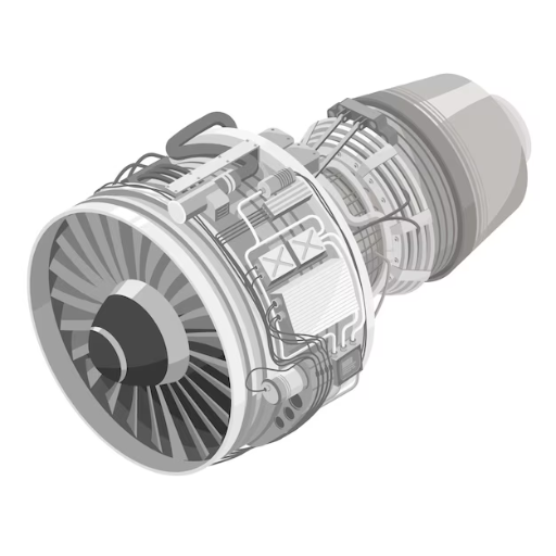
Image source: https://www.freepik.com/
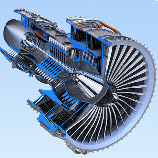
A jet engine consists of multiple major parts that interoperate to create propulsion:
- Fan: The big rotating blades at the front of the engine, which suck in air.
- Compressor: Increases the pressure of incoming air by compressing it before entering the combustion chamber.
- Combustor: Where fuel mixes with high-pressure air and is ignited to produce a high-energy gas flow; also known as combustion chamber.
- Turbine: Utilizes energy from the high-energy gas flow so as to drive compressor and fan.
- Exhaust: Throws out high-speed gas produced by burning fuel within itself outwards through engine, thereby generating thrust that propels aircraft forward.
These are necessary for any jet engine to function properly since they enable conversion of fuel into thrust required for flight.
Overview of Jet Engine Parts
To be brief, here is what makes up a jet engine and its corresponding technical specifications:
- Fan
- Function: Draws in air and accelerates it.
- Technical Parameters: Diameter – usually between 1.5m -3.0m; Number-20-40 blades.
- Compressor
- Function: Compresses incoming air to higher pressure.
- Technical Parameters: Compression ratio (10:1-40:1); Number of compressor stages (5-15).
- Combustor
- Function: Mixes compressed air with fuel then ignites mixture creating high energy gas.
- Technical Parameters: Combustion efficiency (>99%); Temperature range (1400°C -2000°C).
- Turbine
- Function: Extracts some useful work from high energy gases driving both fan and compressor
- Technical Parameters: Turbine inlet temperature (1500°C -1700°C); Turbine pressure ratio (4:1-5:1).
- Exhaust
- Function: Discharges gases at very high speeds producing thrust.
- Technical Parameters: Thrust produced (kN)-80 kN to >400 kN for commercial aviation engines typically.
The Role of the Compressor
A compressor is very important in a jet engine. Its main purpose is to boost the pressure of incoming air before it gets into the combustor. This is done by squeezing the air to a higher pressure which raises its density as well as temperature in return. The rotor and stator are components of each stage that makes up the compressor. Each time the air goes through any stage, it undergoes more compression thus leading to significant increase in exit pressure from this part.
Efficiency and design of compressors are considered key factors for an engine’s performance according to most popular Google search results on this topic. To illustrate better fuel efficiency and higher power output, you can think about increasing compression ratio. Compressor efficiency can be improved through use aerodynamic designs together with advanced materials which also enhance durability Additionally ,variable stator vanes among other innovations enable compressors work optimally at different operating conditions dual spool designs also help achieve.
In conclusion, without the compressor a jet engine would not run efficiently or at all for that matter. It supplies continuous streams of high pressure gases required by combustion chambers necessary for achieving thrust as well performance levels desired in aviation industry today.
Importance of the Turbine in Jet Engines
In jet engines, the turbine plays an important role as it converts the hot and high-pressure gases that are produced in the combustor into mechanical energy. This mechanical energy is then used to operate the compressor and other necessary accessories of the engine. To accomplish this task, the turbine allows exhaust gases to expand as they pass through a number of stages which are made up of rotors and stators. As they go through these stages, they lose energy by giving it up to turbine blades thus causing rotation of rotors.
The overall efficiency and reliability of a jet engine greatly depends on how well its turbines perform; at least according to what Google says. Nickel-based superalloys are commonly utilized as advanced materials since they can withstand extreme temperatures along with stresses encountered within turbines.Furthermore cooling techniques among others thermal barrier coatings have been introduced so as increase durability as well efficiency for different parts making up a turbine.Precise engineering is required during design phase because these devices are supposed work under high rotational speeds , which means that structural stability must be maintained throughout their lifespan under such harsh conditions.
To put it differently, one cannot do without using a turbine in any machine that is powered by combustion of fuel.Turbine’s composition plus its configuration contribute towards ensuring reliability speed performance effectiveness on part jet engines
How Does a Jet Engine Work?
Air Intake and Compression
A jet engine’s starting phase is the air intake. This is where outside air enters the engine through an opening called an intake and then goes to the compressor. The design of this part is made in such a way that it allows enough amount of air at the right speed and pressure to get into the engine.
Once inside, what the compressor does is pumping up its pressure very high. It has many stages consisting of spinning blades and stationary vanes which squeeze it step by step making its pressure as well as temperature higher. In order to combust efficiently during next steps this highly pressurized air is needed. If we want our jet engine works with maximum effectiveness, everything should be accurate at these initial two phases – air inlet and compression.
Combustion and Thrust Generation
Combustion occurs when compressed air from the compressor at high pressure is mixed with fuel, usually jet fuel, and then ignited in a combustor. The main aim of the combustor is to blend the air and the fuel together effectively so that it burns steadily and completely. Heat and energy are introduced into the mixture of air and fuel by this process of combustion which boosts its pressure thus giving rise to high-pressure exhaust gases.
Technical Parameters:
- Combustor Pressure: Typically ranges from 30 to 40 atmospheres.
- Combustor Temperature: Can reach up to 2,000°C (3,630°F).
- Fuel-to-Air Ratio: Approximately 0.02 to 0.03 (mass of fuel to mass of air).
Afterwards these gases pass through a turbine which extracts some work from them to power up the compressor as well as other ancillaries. The design configuration adopted for turbine blades allows for maximum transferability of energy content from these fumes into mechanical work output at their tips while they rotate around their own axis until they reach outer circumference where thrust is produced by accelerated gas particles before being exhausted through nozzle exit section at high speed level.
Technical Parameters:
- Turbine Inlet Temperature: Around 1,400°C (2,550°F).
- Nozzle Exit Velocity: Can exceed 1,500 m/s (approximately 5,000 ft/s).
- Thrust: Depends on engine size, but for commercial aircraft engines, it ranges from 20,000 to 115,000 pounds-force (lbf).
Exhaust Nozzle and Final Propulsion
The final part of a jet engine’s cycle is performed by the exhaust nozzle. In this phase, it converts high pressure and temperature gases into useful thrusts. It is usually designed to narrow progressively thus increasing the speed with which exhaust gases leave the engine. The resultant increase in gas acceleration leads to higher levels of propulsion or thrust that ultimately moves an aircraft forward.
There are different types of nozzles such as convergent and convergent-divergent; however they vary from each other only in design. A converging nozzle works best for subsonic engines since they release gases at very high speeds necessary for plane operation. Conversely, supersonic planes need converging diverging nozzles to efficiently handle accelerated airflow management even past sonic velocity.
Technical Parameters:
- Nozzle Shape: Convergent (subsonic), convergent-divergent (supersonic).
- Thrust Augmentation: Variable geometry nozzles can maximize performance.
- Exhaust Gas Management: Manoeuvrability can be improved through techniques like thrust vectoring.
How Do You Read a Jet Engine Diagram?
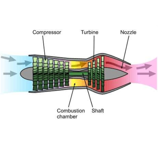
To read a jet engine diagram, you need to know what the different parts are for and how they work together to create thrust. The first thing to do is to identify the main sections: Intake, Compressor, Combustion Chamber, Turbine and Exhaust Nozzle.
- Intake: Air comes into this part of the engine and is directed towards the compressor.
- Compressor: It compresses incoming air by increasing its pressure before it enters the combustion chamber.
- Combustion Chamber: Fuel is injected and ignited in here; mixing with compressed air produces high-temperature high-pressure gases.
- Turbine: These exhaust gases are used to turn turbine blades which will power up the compressor as well.
- Exhaust Nozzle: High-pressure gases are expelled through this area creating forward thrust that moves an aircraft along
Identifying Key Symbols and Labels
Understanding the signs and marks that portray different parts of an engine is necessary to comprehend a jet engine diagram. Here are a few common symbols and labels often found in jet engine diagrams:
- Fan: The fan symbolizes the device at the front of the engine which pulls air into it. A fan is represented by a set of blades.
- Stators and Rotors: Stators (stationary blades) and rotors (rotating blades) are used to direct and compress airflow. Normally shown as rectangular or circular shapes.
- Fuel Injector: This component injects fuel into the combustion chamber. It is usually marked as an injector or nozzle symbol.
- Combustion Chamber: Fuel-air mixture ignites here, flaming icons indicate this part in most cases. It appears as a chamber.
- Turbine: The turbine extracts energy from high-temperature gases produced by burning fuel in the combustion chamber. Shown as curved series of blades.
- Exhaust Nozzle: To create thrust, narrow end of an engine where gases leave; depicted as this nozzle type always appears last when drawing such diagrams.
Understanding the Flow of Air and Fuel
To increase efficiency and thrust, the flow of air and fuel is carefully controlled in a jet engine. This should help you understand better how powerful thrust is generated by these engines:
- Air Intake: Air is pushed into the engine through a fan which raises its pressure.
- Compression: The compressed air is sent to the compressor where stators and rotors work together compressing it further thereby increasing its temperature as well as pressure.
- Combustion: At this point, high-pressure/high-temperature air enters into combustion chamber where fuel gets injected then ignited; this mixture burns thus producing gases with large amounts of energy.
- Turbine Extraction: Rapidly expanding hot gas passes through turbine causing rotation of turbine blades which spins both compressor fan assemblies connected on same shaft hence extracting power from hot gas stream back into mechanical work needed for compression process taking place upstream from.
- Exhaust: Finally remaining gases are let out through an exhaust nozzle creating force that propels aircraft forward.
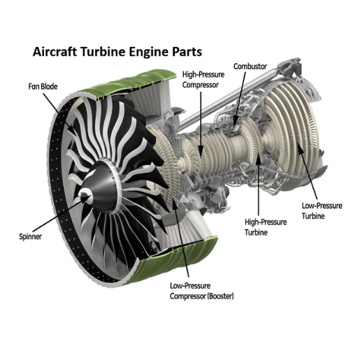
Recognizing the Major Sections of the Engine
In order to fully understand how a jet engine functions, it is important to know the major parts. These are as follows according to three websites:
- Fan: This is the first part of the engine and is found in at the front part. It pulls in a lot of air which is then divided into two; some passes through the core while others bypass it thus generating additional impulse.
- Compressor: The compressor is made up of many stages of rotors and stators working together to squeeze air coming in thereby increasing its pressure as well as temperature.
- Combustor: It is where high-pressure fuel mixes with ignited air. Designed for efficient combustion of fuel so that more energetic gases are created.
- Turbine: A turbine spins when hot gas from combustor flows over/through it. The spinning action drives both compressor and fan connected on same shaft with this section.
- Exhaust Nozzle: Lastly, remaining gases leave engine at great speed through exhaust nozzle which produces forward thrust pushing aircraft ahead.
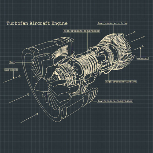
What Is a Turbofan Engine and How Is It Different?
A turbofan engine is a kind of jet engine that combines the features of both turbojet and turboprop engines, focusing on efficiency and performance. This type of engine differs from the traditional turbojet engines by accelerating air only through its central core. On the other hand, it is equipped with a fan at the front part which takes in a greater amount of air. After that, this air gets split whereby some passes through the engine core where it gets compressed, mixed with fuel and ignited while the rest bypasses the engine core flowing around it through another duct.
Below are some key differences of turbofan engines:
- Bypass Ratio: This refers to how much air goes past an engine compared to what goes through it. Engines with higher bypass ratios are more efficient.
- Fuel Efficiency: Turbofans have better fuel efficiency especially at lower speeds making them suitable for commercial aviation.
- Noise Reduction: Turbofans help reduce noise produced during operation due to their design which incorporates large volumes of bypassed airs that acts as silencers for exhaust sounds from these engines.
Basics of a Turbofan Engine
Let’s break down the basic parts of a turbofan engine and what they do:
- Fan: The large front fan in the engine draws in a large amount of air. This air is split into two streams, one that bypasses the engine core and another which goes through it.
- Compressor: Located in the engine core, this part increases the pressure of incoming air before it reaches the combustion chamber. This step is essential for fuel to be burned efficiently.
- Combustion Chamber: Compressed air is mixed with fuel and then ignited here, creating high-pressure and high-temperature gases. The ignition provides energy for moving an aircraft forward.
- Turbine: The turbine spins as hot gases from combustion chamber expand through it. It is connected to both compressor and fan, so that mechanical energy required to keep them running is supplied by it.
- Exhaust: The remaining gases leave an engine via exhaust nozzle where thrust is produced. In a turbofan engine, efficient thrust generation results from core exhaust combined with bypassed air.
Comparing Turbofan and Turbojet Engines
Comparing turbofan and turbojet engines reveals a number of key differences that affect their use in different aircraft types.
- Efficiency:
- Turbofan Engines: Turbofans are built for higher efficiency especially at lower speeds and altitudes typical of commercial airliners. They have a better thrust-to-fuel consumption ratio because of the bypass air it produces thus making them more fuel efficient over long distance flights.
- Turbojet Engines: More efficient at higher speeds and altitudes which are ideal for supersonic flight; however, they consume more fuel hence less efficient for subsonic travel as compared with turbofans.
- Thrust:
- Turbofan Engines: It generates thrust from both the jet core as well as bypass air. A large fan is responsible for producing significant amount of thrust thereby enhancing smoothness during operation also contributing to reduced noise levels.
- Turbojet Engines: In this case, majority (if not all) the thrust is produced through exhaust gases emanating from the jet core hence resulting into rougher operation with higher noise level produced.
- Noise:
- Turbofan Engines: Turbofans tend to be quieter due to mix of bypass air and core exhaust, making them suitable for commercial aviation where noise pollution is an issue.
- Turbojet Engines: The fact that all air passes through core causes these engines to be noisy as there is more turbulent exhaust outflow created.
- Applications:
- Turbofan Engines: They are widely used in commercial airliners and transport aircrafts due to their fuel efficiency together with reduced noise levels during operation which makes them quiet while flying over populated areas or during takeoff/landing phases at airports surrounded by residential neighborhoods.
- Turbojet Engines: Mainly utilized in military planes plus supersonic jets where very high speed & performance are required but not necessarily economic considerations such as in civil aviation; here fuel economy takes second place after power output/output power ratio based on design requirements like range etcetera needed by armed forces or for combat purposes.
Turbofan Engines in Modern Aviation
Where Can You Find High-Quality Jet Engine Diagrams?
You can get diagrams of high quality jet engines from a number of trusted sources:
- Manufacturers’ Websites: Websites which are official for top jet engine manufacturers like Rolls-Royce, General Electric and Pratt & Whitney often give detailed technical diagrams and animations.
- Aviation Textbooks and Manuals: Aviation engineering comprehensive guides and textbooks usually have detailed explanations together with them high-quality diagrams.
- Online Databases and Portals: Technical documents such as precise jet engine diagrams can be found on websites like NASA’s Technical Reports Server or resources offered by FAA (Federal Aviation Administration).
- Aviation Magazines and Journals: Journals that are industry specific both online and in print regularly publish analytical diagrams as well as high-res images of different types of jet engines.
Best Sources for Stock Photos and Illustrations
To find the best stock photos and illustrations, many people turn to three websites:
- Shutterstock: This is one of the biggest and most popular stock photo sites. Shutterstock has millions of high-quality images, vectors, videos, and illustrations. It covers almost every topic you can think of with an incredibly wide range of content.
- Adobe Stock: Adobe Stock easily integrates with all Adobe Creative Cloud applications which makes it convenient for designers or creatives who use Adobe tools. They offer a huge catalog filled with professional-grade 3D assets along with graphics and photos.
- iStock by Getty Images: iStock boasts an extensive collection that includes various types such as exclusive higher-end pictures as well as more affordable options found in their Essentials collection among others.
Using Jet Engine Diagrams in Education and Training
In aviation, jet engine diagrams are of great importance when it comes to learning and training for individuals working in this field; this applies to both students and professionals. These drawings give a visual representation of the inner parts of a jet engine which are usually quite complicated thereby simplifying the understanding its operational principles. Educators can use high-quality images and illustrations obtained from reputable sources like Shutterstock, Adobe Stock or iStock by Getty Images among others so as to enrich their teaching aids with accurate and captivating visuals.
Shutterstock boasts an extensive collection comprising various types of diagrams for jets engines that can be integrated into presentations or training manuals thus ensuring that learners have access to detailed and precise representations. With seamless integration into Creative Cloud applications, Adobe Stock enables teachers create personalized educational materials which may include professional grade graphics designed to clarify complex ideas. On the other hand, iStock offers options at different price points including both high-end and pocket friendly ones making it possible for premium quality visual aids be used even in institutions operating on tight budgets. By utilizing these resources, educators together with instructors will be able enhance learning through provision clear, comprehensive as well visually stimulating materials meant for better understanding jet technologies among students.
Royalty-Free Images and Their Benefits
Individuals and organizations who want high-quality visual content without the complex licensing agreements are often recommended to use royalty-free images. They come with a lot of advantages which are as follows:
- Cost Efficiency: A single payment is usually needed for this type of image which means that after the purchase has been made, one can use it as many times as possible without having to make any other payments or royalties thus making them cheap for both small businesses and individuals working in the field of education.
- Variety and Quality: Platforms like Shutterstock, Adobe Stock or iStock by Getty Images offer their users an opportunity to choose from thousands upon thousands of different pictures taken at various angles so there is always something suitable no matter what kind of promotional materials you need them for.
- Legal Protection: It’s hard not to be legally protected when using Royalty free images since most licenses cover nearly all uses while also preventing copyright issues from arising.
- Flexibility: The fact these pictures can be used on different projects (websites, social media platforms, printed materials) without asking anyone for another permission makes them really handy especially if you’re someone who does lots of work in this area.
Reference sources
-
NASA – Engines at Glenn Research Center
- NASA provides a thorough explanation of jet engines, including detailed diagrams and descriptions of their components and operations. This resource is invaluable for understanding the fundamental principles of how jet engines produce thrust and function.
- Source: NASA
-
Stanford University – How The Jet Engine Works
- This resource from Stanford University offers an animated illustration of jet engine processes such as air inflow, compression, combustion, and air outflow. It’s a comprehensive guide to visualizing and understanding the operational stages of a jet engine.
- Source: Stanford University
-
Boldmethod – How Does A Turbofan Engine Work?
- Boldmethod provides a detailed breakdown of turbofan engines, explaining how they operate by sucking air into the front using a fan, compressing it, combusting it with fuel, and then expelling it to generate thrust. This source includes insights into the different parts of the engine and their specific functions.
- Source: Boldmethod
Frequently Asked Questions (FAQs)
Q: What is a gas turbine engine?
A: A gas turbine engine is a type of engine that converts natural gas or other liquid fuels to mechanical energy, which is then used to power an aircraft. It works by compressing air, mixing it with fuel, and igniting it to produce high-velocity exhaust gases.
Q: How do compressor blades function in a jet engine?
A: Compressor blades play a crucial role in a jet engine by compressing the incoming air before it enters the combustion chamber. This compression increases the air pressure, which is essential for efficient fuel combustion.
Q: Can I find stock photos and images available of jet engines?
A: Yes, there are many stock photos and images available, including jet engine diagram stock illustrations, which can be useful for educational and professional purposes.
Q: What parts of a jet engine can be seen in a diagram of a typical gas turbine engine?
A: A diagram of a typical gas turbine engine includes parts such as the compressor, combustor, turbine, and sometimes a propeller for certain types of engines.
Q: Are there royalty-free photos of jet engines for educational use?
A: Yes, there are various royalty-free photos available that can be used for educational purposes. These include detailed images of the outside of the engine, side views, and the back of the engine.
Q: What does a stylized vector illustration of drawings of a turbofan engine look like?
A: A stylized vector illustration of drawings of a turbofan engine typically includes simplified and artistic representations of the engine components, often in a 2D format, which makes them ideal for presentations and educational materials.
Q: How is a 3D rendering of a large passenger plane jet engine different from other images?
A: A 3D rendering of a large passenger plane jet engine provides a detailed, three-dimensional view of the engine, allowing for a more comprehensive understanding of its structure and function, unlike 2D stock pictures or vector illustrations.
Q: What kind of roles do a team of three aircraft engineers or aircraft mechanics in the hangar perform?
A: A team of three aircraft engineers or aircraft mechanics in the hangar is typically responsible for conducting maintenance, repairs, and inspections around the engine to ensure the aircraft is in optimal condition.
Q: Are there stock illustrations or stock pictures that show the side view of an aircraft gas turbine engine?
A: Yes, there are stock illustrations and stock pictures that provide a side view of an aircraft gas turbine engine, which can help in understanding the layout and components of the engine.
Q: How helpful can a jet engine diagram stock illustration with a white background be?
A: A jet engine diagram stock illustration with a white background is very helpful for clear and focused presentation. It eliminates distractions, making the parts of the jet engine more visible and easier to study.