

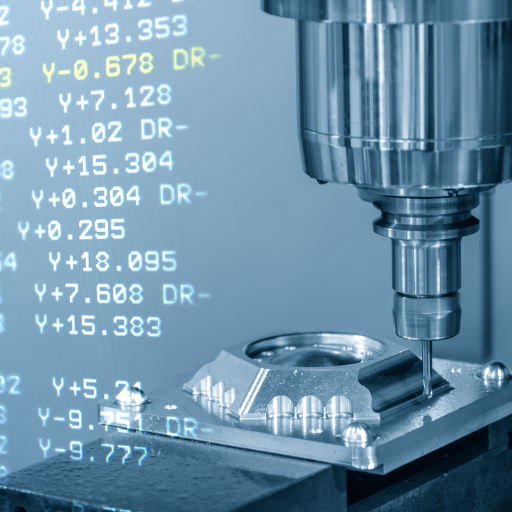
What is G-Code and How Does it Work?

Image source: https://marketplace.visualstudio.com/
Understanding the Basics of G-Code
Why G-Code is Essential for CNC Machines and 3D Printers
How to Read G-Code Commands?
The Role of Line Numbers in G-Code
Deciphering Common G-Code and M-Code Commands
In the world of CNC machining, G-Code and M-Code commands are essential for dictating the operations of CNC machines. Understanding these commands is crucial for precise and efficient machining processes.
Common G-Code Commands
- G00 (Rapid Movement):
- Function: This moves the tool at the highest velocity to a specified coordinate.
- Example: `G00 X10 Y20 Z5`
- G01 (Linear Interpolation):
- Function: The tool follows a straight path at a set feed rate.
- Example: `G01 X10 Y20 F150`
- G02 (Clockwise Circular Interpolation) and G03 (Counter-Clockwise Circular Interpolation):
- Function: The tool will move in circular paths along either clockwise (G02) or counter-clockwise (G03) directions.
- Example: `G02 X20 Y25 I5 J5`
Common M-Code Commands
- M00 (Program Stop):
- Function: This completely stops the operation of CNC machine until resumed manually by an operator.
- Example: `M00`
- M03 (Spindle On, Clockwise) and M04 (Spindle On, Counter-Clockwise):
- Function: This turns on the spindle in the direction indicated.
- Example: `M03` or `M04`
- M05 (Spindle Stop):
- Function: This halts rotation of spindle.
- Example: `M05`
- M30 (Program End and Rewind):
- Function: The program comes to an end, rewinds to its start point.
- Example: `M30`
Breakdown of the Syntax for G-Code Programming
A good understanding of G-Code programming syntax is crucial to enable efficient control of CNC machines. Below is a simplified version of common components and syntax that takes into consideration the insights from various sources.
- Line Number (`N`):
- Usage: Describes the order in which instructions are given.
- Example: `N10 G01 X10 Y10`
- G-Commands (Preparation Codes):
- Usage: Sets up the machine for specific motion types or mode settings.
- Example: `G00` for rapid movement, `G01` for linear interpolation.
- Coordinate Values (`X`, `Y`, `Z`):
- Usage: Shows where the tool is located along each axis.
- Example: `X10 Y20 Z30`
- Feed Rate (`F`):
- Usage: Dictates how quickly the tool moves.
- Example: `F150` sets the feed rate to 150 units per minute.
- Spindle Speed (`S`):
- Usage: Specifies spindle rotation speed.
- Example: `S500` means the spindle rotates at 500 revolutions per minute (RPM).
- Tool Selection (`T`):
- Usage: Determines exact tool to be used in performing an operation.
- Example: `T01` selects tool 1.
- Miscellaneous Functions (`M`):
- Usage: Performs additional tasks such as starting or stopping a motor.
- Example: `M03` turns the spindle on clockwise, `M05` stops the spindle.
The most common G-code commands
To program CNC machines, you need to know about G-codes, specifically some most frequently used ones. Let us now look at each of them.
- G00 – Rapid positioning: Moves the tool along a straight line.
- G01 – Linear interpolation: Moves the tool from one point to another in a straight line.
- G02 – Circular interpolation (clockwise): Makes an arc by moving the tool in a clockwise direction.
- G03 – Circular interpolation (counterclockwise): Moves the tool around in a counterclockwise circle.
- G20 – Set units to inches: Specifies that measurements are in inches.
- G21 – Set units to millimeters: Specifies that measurements are in millimeters.
- G28 – Return to home position: It tells the machine that it should go back to the home position which has been preprogrammed for it.
- G90 – Absolute Positioning Mode”: Absolute positioning set coordinates as the distance of the current point from zero-points.
- G91 – Incremental Positioning”: Everything is done relative to last position guints are always based on previous values until changed.
G01: Moving in a Straight Line with Feed Rate
G28: Returning to Home Position
G21 vs G20: Metric vs Imperial Unit System
How is the Coordinate System Managed in G-Code?
Understanding XY and Z Axes in G-Code
The three-dimensional coordinate system used to control the movement of CNC machines is defined by the X, Y and Z axes in g-code. The X axis is mainly associated with horizontal movements from left to right on a machine table while the Y axis represents horizontal changes from front to back. The Z axis on its part signifies vertical movements up and down. These axes make it possible for cutters or workpieces to be positioned accurately.
This means that G-Code commands are used to tell the machine where it should move or cut along these axes. For instance, `G01 X10 Y20 Z-5` will shift a tool ten units along the x-axis, twenty units along y-axis and five units towards z-axis lower. Thus understanding how these axes operate is essential for precise and efficient machining operations that ensure adherence of cutter paths based on design specifications.
Using G90 for Absolute Positioning
G-Code Commands for Coordinate System Management
To achieve high levels of precision and repeatability in complex operations, it is of essence that CNC machining coordinates are managed properly. These commands give machinists the ability to define what a coordinate system encompasses and how they can manipulate them for their purpose.
G54 to G59
Commands like `G54` – `G59` help select different work coordinate systems. Each code corresponds to unique zero points pre-set by the machine operator. For instance, when used as an example, G55-G59 could be various toolset-ups for multi-stage manufacturing where different zeros may be necessary.
G92
`G92` is a command used to determine machine position. You can initiate this order “G92 X0 Y0 Z0” so that your present location will serve as the reference point without physically changing the position of your machine. This feature becomes useful especially when you restore origin at a new point after tool change or part adjustment.
G10
On the other hand, G10 is able to offer more flexible adjustments within the coordinate system. By specifying values on axes, one can use ‘’G10’’ either as a setting or an editing function that augments assignation of offsets on any present coordinate group. Take for instance; G-Code “L2 P1 X0 Y0 Z0” would establish current position as zero relative to work coordinate system 1 (‘’G54’’).
Best tools and editors for G-code programming
There are different tools and editors that can be used in order to optimize the G-code programming, with each one having its own unique functions that will help improve productivity or precision. Some of the popular options include:
- CAM Software: Programs like Mastercam, Fusion 360, and SolidWorks CAM combine CAD and CAM capabilities within one package enabling users to develop components and generate G code.
- Dedicated G-Code Editors: The likes of NC Viewer, G-Code Simulator, or G-Wizard are some of these editors that have incorporated features such as syntax highlighting, error checking as well as simulation for visualizing tool paths or detecting issues before embarking on production.
- Text Editors: Advanced text editors such as Sublime Text, Notepad++ or VS Code can be customized using g-code extensions which offer basic editing functionalities and syntax highlighting thus suiting small changes and manual coding.
- Machine Manufacturer Software: Many CNC machine manufacturers provide their proprietary software tailored to their machines like FANUC’s G-Code Editor or Haas CNC Control Software for compatibility reasons and optimized performance.
Choosing the Best G-Code Editor for Your Needs
When selecting the best G-code editor, it is important to assess the software in terms of ease of use, functionality and specific needs of your projects. Here are some considerations that would come to mind if they came across these websites:
- User Experience and Interface:
- Consider looking for intuitive interfaces that can be customized. For instance, Fusion 360 and Autodesk Inventor HSM provide user friendly dashboards that make G-code creation and simulation easier for beginners as well as professionals.
- Functionality and Features:
- Check what kind of features this software has to offer. For example, Fusion 360 has comprehensive CAD and CAM capabilities while Mach3 offers extensive support for various CNC operations as well as Notepad++ with broad text editing functionalities having syntax highlighting which can be adjusted for G-Code.
- Community and Support:
- Is there any community support or official customer service? Active users’ communities as well as extensive online documentation are a key attribute of such software like Fusion 360 or Mach3 which are meant to give room for trouble shooting and learning advanced aspects respectively.
Tools that Simplify G-Code Programming and Editing
Three standout options can be pointed out with the help of insights from the current top-rated websites, which would then provide guidelines for choosing effective tools that would simplify G-Code programming and editing.
- Fusion 360:
- Autodesk’s Fusion 360 is one of the heaviest CAD and CAM tools supporting a variety of manufacturing processes. It combines design, engineering, and production under one platform facilitating seamless G-code generation. The software boasts integrated CAM functions and simulation tools for thorough testing and validation of g-codes before actual machining hence reducing errors in the process.
- Mach3:
- Mach3 is versatile control software that supports many CNC operations making it popular among hobbyists and professionals. Some of its key features include adaptable user interfaces as well as extensive control capabilities for different types of CNC machines. Mach3 also has strong community support coupled with comprehensive documentation which are vital in troubleshooting as well as optimizing G-Code.
- Notepad++:
- Notepad++ is an efficient text editor widely used for various programming languages such as g-codes. The program comes with syntax highlighting, macro recording abilities and customizable user interface hence promoting swift g-code editing procedures. The attraction to Notepad++ is due to its light weightiness and easiness in integration into other tools within your editorial workflow thus making it a good suit for fastidious g-code edits.
How to Use G-Code in CNC Machining?
When using G-Code in CNC machining, you need to do the following steps:
- Create or Obtain a Design:
- Using CAD software, make an elaborate design of the part or get an existing design. It should be accurate and precise because it will dictate movements of the machine.
- Generate G-Code:
- Use CAM software to transform the design into G-code. During this process, a CAM program translates the model into instructions that can be understood by CNC machines. Ensure that the produced code is optimized for efficiency and accuracy.
- Upload G-Code to CNC Machine:
- In order for it to start work after that securing of work piece must be done as well as selection of appropriate tools which will operate on thus ensuring that all safety checks have been completed.
- Setup the Machine:
- Prepare the CNC machine for operation by securing the workpiece and selecting the appropriate tools. Ensure that all safety checks are completed.
- Run and Monitor the Machining Process:
- The next step involves executing your g code on a cnc machine followed by close monitoring during which any anomalies are identified in course of machining. Adjustments are important since they contribute towards precision and quality.
G-Code in CNC Milling and CNC Turning
In CNC milling and turning, the G-Code is vital as it dictates how different tasks will be done by the machine. For instance, when it comes to CNC milling, G-code tells the machine how to move the cutting tool for shaping or creating intricate designs on a workpiece. It also covers factors such as drilling, contouring and pocketing. Commonly used are commands like G01 (linear interpolation), G02/G03 (circular interpolation).
On the other hand in CNC turning, there are G-Code commands that enable a tool to move as material is removed from a spinning workpiece resulting in cylindrical components. Speed control and quality improvement may require instructions like G50 (spindle speed limit) or even G96 (constant surface speed). In order to manufacture complex and highly detailed parts both processes of machining employ g-code which guarantees high precision and repeatability.
An Overview of G-Code for Machine Tools and Spindle Control
G-Code is the language that is used for programming CNC machine tools and controlling spindle operations. For instance, G-Code commands determine what a machine tool should do, such as positioning the cutting tool, controlling feed rates and performing other machining operations. The widely-used G00 (rapid positioning) command as well as G01 (linear interpolation) and G02/G03 (circular interpolation) which specify detailed workpiece movements.
G-Code also controls spindle’s speed and rotational direction. Commands like M03 are used to start and regulate the clockwise rotation of a spindle while M04 initiates its counterclockwise movement. In addition to this, M05 indicates spindle stop. Other commands such as S1000 set spindle speed to 1000 RPM allowing for a better product quality due to effective control of machining conditions.Consequently, by using G-code effectively, CNC operators can achieve high accuracy levels in their modern production environment.
Importance of G-Code in CNC Programming and CNC Machine Operation
G-Code is essential in CNC programming and machine operation since it translates instructions from the design into exact movements and actions of the machine. There are several reasons behind its significance:
- Precision and Accuracy: It is possible to use G-Code commands to achieve surgical accuracy in executing all cutting, boring or finishing moves. This kind of precision is necessary for manufacturing intricate components.
- Efficiency and Consistency: Through automation of the machining process, G-Code saves on time increasing productivity. Operations are standardized thus reducing human errors while ensuring a consistent quality across batches.
- Flexibility and Versatility: G-Code can work with various types of CNC machines as well as perform many kinds of machining operations. For example, different materials or design specifications necessitate quick adjustments or fine-tuning processes.
- Optimized Workflow: Good application of G-Code commands enables optimization spanning through tool positioning to spindle speed control resulting in extended tool life, shorter cycle times and better end-products. Manufacturers can therefore increase their efficiency by using G-Codes.
Reference sources
-
Wevolver – Your Guide to 3D Printing G-Code
- This guide offers a thorough understanding of G-Code in the context of 3D printing, detailing its importance, how it operates, and the fundamental commands necessary for effective 3D printing.
- Source: Wevolver
-
Creality Cloud – G-Code List: Essential Commands for Your 3D Printer
- Creality Cloud provides an essential list of G-Code commands used in 3D printing. It explains the significance of each command and how mastering these can enhance your 3D printing capabilities.
- Source: Creality Cloud
-
Amazon – Unlock the Power of G-Code: Master CNC Machining and 3D Printing
- This book is a definitive guide to mastering G-Code programming for both CNC machining and 3D printing. It covers comprehensive techniques and practical tips for leveraging G-Code in digital fabrication.
- Source: Amazon
Frequently Asked Questions (FAQs)
Q: What is G-Code and why is it important in CNC programming and 3D printing?
A: G-Code is a numerical control programming language used to control CNC machines and 3D printers. It consists of various code commands that tell the machine how to move, what speed to maintain, and other essential operations. Mastering G-Code is crucial because it allows for precise control and customization of machining and printing processes.
Q: How does a machine controller use G-Code?
A: A machine controller interprets the G-Code file and converts each line of G-Code into specific actions for the CNC machine or 3D printer. This includes moving to coordinates, starting and stopping the spindle, adjusting speeds, and other tasks. The controller ensures that the commands are executed accurately and efficiently.
Q: What are some commonly used G-Code commands and what do they do?
A: Some commonly used G-Code commands include: G00 (rapid positioning), G01 (linear interpolation), G02 (circular interpolation clockwise), G03 (circular interpolation counterclockwise), and G28 (return to home). Each command starts a specific machine action, and there are many more commands to set various parameters like feed rate and spindle speed.
Q: What is a line of G-Code?
A: A line of G-Code, also known as a block, is a single instruction in a G-Code program. Each line typically contains a command and its parameters, instructing the machine on a specific action to perform. Lines of G-Code help in breaking down complex tasks into manageable steps that the machine can execute sequentially.
Q: How do you create and edit a G-Code file?
A: Creating and editing a G-Code file involves writing the G-Code commands in a text editor or a specialized G-Code editor. Many users start with a G-Code tutorial to learn the basics. Advanced users might use CAD/CAM software that generates G-Code automatically based on a 3D model. The best G-Code editing tools offer features for error checking and simulation.
Q: What is a canned cycle in G-Code programming?
A: A canned cycle is a pre-programmed sequence of operations that can be executed by a single G-Code command. Canned cycles are commonly used for repetitive tasks like drilling, tapping, or boring. They simplify the code programming by reducing the number of lines of code needed for these operations.
Q: What resources are available to learn G-Code programming?
A: There are numerous resources to learn G-Code programming, including online tutorials, courses, books, and forums. A thorough G-Code tutorial can provide step-by-step instructions for beginners. Additionally, software simulations and hands-on practice with CNC machines or 3D printers can enhance understanding and skill.
Q: Why is understanding the G-Code programming language essential for operating CNC lathes and 3D printers?
A: Understanding the G-Code programming language is essential because it allows operators to customize and optimize the machining or printing process. Knowing how to read and write G-Codes enables users to troubleshoot issues, make adjustments on the fly, and fully utilize the capabilities of CNC lathes and 3D printers.
Q: What are some challenges one might face when learning G-Code, and how can they be overcome?
A: Some challenges in learning G-Code include understanding the syntax, memorizing commonly used commands, and knowing how to apply the commands correctly. These can be overcome with practice, seeking help from online communities, and using tools that visualize the G-Code work. Many find that starting with a simple project and gradually taking on more complex tasks helps in building confidence and skill.