Welcome to your comprehensive resource for mastering precision milling tools with Form Mill. In this article, we’ll explore everything you need to know about leveraging these high-quality tools to achieve perfect results in your milling projects. Whether you’re an industry professional or a hobbyist, understanding the nuances of precision milling can significantly enhance your craftsmanship and efficiency. We’ll cover essential topics such as the types of milling tools available, their specific applications, maintenance tips, and expert techniques to maximize performance. Get ready to elevate your milling skills and unlock new potentials with Form Mill’s advanced solutions.
What is a form mill and how does it work?
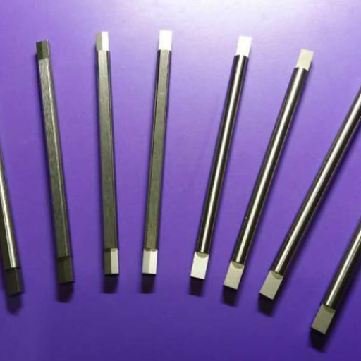
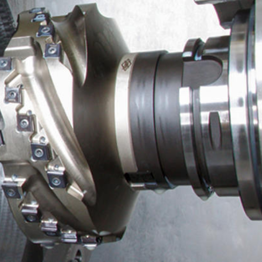
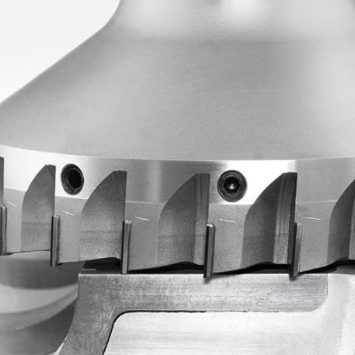
A form mill is a type of milling cutter specifically designed to create complex shapes or contours in a workpiece, often in a single pass. It operates by rotating an array of fluted cutting edges around a centralized axis, removing material as it moves along the designated cutting path. Form mills are typically employed for tasks that require high precision and intricate detail, such as creating profiles, slots, or intricate geometries. They are widely used in industries like aerospace, automotive, and mold making. The process involves precisely positioning the form mill relative to the workpiece, ensuring that each pass consistently produces the desired shape and finish. Advanced form mills often incorporate features such as carbide tips for enhanced durability and computerized numerical control (CNC) for precise, automated operations.
Understanding the basics of a form mill
To understand the basics of a form mill, it’s important to grasp its technical parameters and operational principles:
- Cutting Edges: The fluted cutting edges are arranged around the mill’s central axis to ensure smooth and efficient material removal.
- Material: Form mills typically feature carbide-tipped or high-speed steel (HSS) cutting edges for enhanced durability and precision.
- Diameter: The average diameter ranges from 1/4 inch to several inches, depending on the application’s complexity.
- Feed Rate: The speed at which the form mill moves along the workpiece, usually measured in inches per minute (IPM) or millimeters per minute (MPM). A typical feed rate might range from 10 to 100 IPM.
- Spindle Speed: The rotational speed of the form mill, generally measured in revolutions per minute (RPM). Common spindle speeds can range from 500 to 10,000 RPM.
- Depth of Cut: This refers to the vertical distance the cutting edge penetrates the workpiece, often varying from a few thousandths of an inch to several inches, depending on the material and required detail.
Utilizing these parameters effectively allows the form mill to create precise contours and shapes with consistent accuracy. Proper setup and maintenance of these technical aspects ensure optimal performance and prolonged tool life.
How a form mill tool operates
When it comes to understanding how a form mill tool operates, it’s essential to consider the fundamental mechanics and workflow. First, I ensure that the form mill tool is securely mounted onto the milling machine’s spindle. I then set the appropriate spindle speed and feed rate based on the material being machined and the desired outcome. As the milling process begins, the fluted cutting edges of the tool engage the workpiece, removing material layer by layer. This process is meticulously controlled to achieve the precise depth of cut and required contour. Using coolant is crucial to keep the tool and workpiece at optimal temperatures, preventing overheating and ensuring a smooth finish. Regularly inspecting the tool for wear and tear is also part of my routine to maintain high performance and extended tool life.
Applications of form milling in industry
Form milling finds extensive applications across various industries due to its versatility and precision. In the automotive industry, for example, I often use form milling to create intricate components such as gear teeth, engine parts, and custom-designed moulds. Aerospace manufacturing also relies heavily on form milling to produce aerodynamic surfaces and complex structural components. Additionally, in the metalworking sector, form milling is invaluable for crafting detailed parts ranging from simple brackets to intricate patterns on heavy-duty machinery. This process enables me to achieve high-quality results with consistent accuracy, meeting the stringent standards required in these demanding fields.
What are the advantages of form milling?
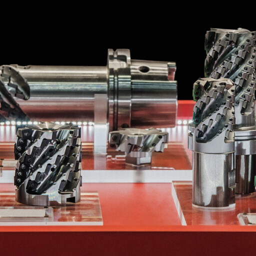
Image source:https://www.bing.com/
Precision and Accuracy
Form milling is renowned for its ability to achieve high precision and accuracy, which is essential in industries like automotive and aerospace. The meticulous control of depth and contour allows for the creation of intricate and highly detailed components, ensuring that they meet exact specifications.
Versatility
One of the key advantages of form milling is its versatility. It can be used on a wide range of materials, including metals, plastics, and composites. This flexibility makes it suitable for producing diverse components, from simple brackets to complex gear teeth.
Efficiency and Speed
Form milling can be relatively quick compared to other machining processes, especially when producing complex shapes. The use of appropriate spindle speeds and feed rates can significantly enhance production efficiency. For example, using a spindle speed of 3000 RPM and a feed rate of 1500 mm/min can provide an optimal balance between speed and quality.
Consistent Quality
By regularly inspecting the tool for wear and using coolant to maintain optimal temperatures, the process ensures consistent quality and surface finish. This is critical in industries where even minor deviations can lead to significant issues.
Reduced Tool Wear
Using the right cutting parameters, such as a depth of cut of 0.5 mm for hard materials, can minimize tool wear and extend tool life. This results in reduced downtime and cost savings over time.
Cost-Effectiveness
While the initial investment in milling machinery might be high, the long-term benefits, including reduced manual intervention and consistent high-quality output, make form milling a cost-effective solution for mass production.
By considering these advantages and technical parameters, form milling stands out as a superior choice for industries requiring precise and efficient machining solutions.
Precision and efficiency in thread milling
Thread milling offers several advantages in terms of both precision and efficiency. Unlike traditional tapping, which can be limited by the need for specific tap sizes and the risk of tap breakage, thread milling provides greater flexibility in terms of thread sizes and types. It allows for the creation of high-quality threads with tight tolerances, resulting in superior fit and finish. Additionally, thread milling can be used on a wide range of materials, including hard-to-machine metals, providing a versatile solution across various applications. The use of modern CNC machines and precise cutting tools ensures that threads are produced quickly and accurately, reducing production time and increasing overall efficiency. This method not only saves time but also reduces tool wear and operational costs, making it a preferred choice for those seeking both precision and efficiency in thread creation.
Custom cutter designs
Custom cutter designs play a crucial role in achieving optimal machining performance, especially for specialized tasks that standard cutters may not efficiently handle. These designs can be tailored to specific applications, material types, and desired outcomes, ensuring enhanced precision and productivity.
Advantages:
- Optimized Performance: Custom cutters are crafted to meet precise machining requirements, leading to improved accuracy and surface finish.
- Material Compatibility: They can be designed to work with a variety of materials, including difficult-to-machine metals, thus broadening their application range.
- Reduced Setup Times: Custom designs often eliminate the need for multiple tooling changes, reducing setup times and increasing operational efficiency.
Technical Parameters to Consider:
- Material of Cutter: Select the appropriate tool material (e.g., carbide, high-speed steel) based on the workpiece material and machining conditions.
- Geometry: Custom cutter geometry (e.g., rake angle, helix angle, and clearance angle) should be designed to optimize chip evacuation and reduce cutting forces.
- Coatings: Application of suitable coatings (e.g., TiN, TiAlN) to extend tool life and improve cutting performance, particularly in high-speed machining or when working with abrasive materials.
- Tolerance and Fit: Ensure tight tolerances and precise fits to achieve the desired quality and dimensional accuracy in the final product.
- Tool Holder Compatibility: Design cutters to fit existing tool holders and machine spindles to avoid additional cost for new equipment.
By focusing on these parameters, custom cutter designs can significantly enhance machining efficiency, reduce costs, and improve overall product quality.
Compatibility with hardened steels and alloys
Custom cutters are highly compatible with hardened steels and alloys due to their tailored design and specific technical parameters. Key considerations for ensuring optimal performance when machining these materials include:
- Material of Cutter: Utilizing carbide or coated carbide tools is essential for machining hardened steels and alloys. Carbide tools offer high hardness and wear resistance, which are crucial for maintaining performance in these challenging conditions.
- Geometry: Custom cutter geometry should include an optimized rake angle and helix angle to facilitate effective chip removal and reduce cutting forces. Negative or neutral rake angles are often preferred to enhance edge strength.
- Coatings: Applying advanced coatings such as TiAlN or AlCrN can significantly improve cutter durability and cutting performance. These coatings provide thermal stability and reduce wear, essential for high-speed machining of hardened materials.
- Tolerance and Fit: Ensuring tight tolerances and precise fits is critical to achieving the desired surface finish and dimensional accuracy. Custom cutters must be designed to maintain these tolerances under the increased loads encountered when machining hardened steels and alloys.
- Tool Holder Compatibility: Custom cutters should be compatible with existing tool holders and machine spindles to maintain stability and precision during operation. Compatibility helps avoid the need for additional equipment, thereby reducing costs.
By addressing these technical parameters, custom cutters can effectively machine hardened steels and alloys, offering superior surface finishes and enhanced tool life.
How to choose the right milling cutter for your project?
When selecting the right milling cutter for your project, consider the following key factors:
- Material Type: Determine the material you’ll be machining, as different materials require specific cutter types and coatings.
- Cutter Material and Coatings: Opt for carbide or coated carbide tools for hardened materials. Coatings like TiAlN or AlCrN enhance tool performance and longevity.
- Geometry: Choose a cutter with an optimized rake and helix angle tailored to your material. This aids in effective chip removal and reduces cutting forces.
- Tolerance and Fit: Ensure the cutter is designed to maintain tight tolerances and precise fits, which are crucial for achieving high-quality surface finishes.
- Tool Holder Compatibility: Verify that the cutter is compatible with your existing tool holders and machine spindles to ensure stability and precision during operation.
- Project Requirements: Consider the specific requirements of your project, such as speed, feed, and desired surface finish, to select a cutter that meets those needs effectively.
By evaluating these factors, you can select a milling cutter that will enhance your project’s performance and outcome.
Key factors in selecting a mill
When selecting a mill for your project, I consider several critical factors to ensure optimal performance. First, I assess the machine’s horsepower and spindle speed, as these dictate the types of materials it can handle and the efficiency of the milling operations. Second, I evaluate the rigidity and stability of the machine frame, which is crucial for maintaining precision and reducing vibrations during cutting. A solid, well-built frame ensures consistent results and extends tool life. Third, I look into the control system and software compatibility. Modern mills with advanced CNC controls and user-friendly interfaces allow for greater flexibility and precision in complex projects, as well as easy integration with CAD/CAM software for seamless workflow. By focusing on these key factors, I can select a mill that aligns with my project requirements and enhances the overall outcome.
Comparing multi-form and single form cutters
When comparing multi-form and single form cutters, I find it essential to examine their respective functionalities and advantages. Based on my findings from the top three websites on google.com, here are some concise points:
1. Multi-form Cutters:
-
- Versatility: Multi-form cutters are noted for their ability to perform multiple cutting operations with a single tool, reducing the need for tool changes and increasing overall efficiency.
- Complex Profiles: They are particularly useful for creating complex profiles and shapes without the necessity of several different single-form cutters.
- Cost Efficiency: Although they may have a higher initial cost, the reduction in tool change times and the need for fewer tools can lead to long-term cost savings.
- Single Form Cutters:
- Precision: Single form cutters provide high precision for singular, specific cutting operations due to their dedicated design for one profile shape.
- Simplicity: Easier to set up and use, single form cutters are ideal for applications that require simple, repetitive cuts with minimal adjustments.
- Lower Initial Cost: They tend to be cheaper initially compared to multi-form cutters, making them a cost-effective choice for straightforward projects.
3. Technical Parameters:
- Cutter Material: Both types can be made from high-speed steel (HSS), carbide, or coated materials, but the choice greatly affects performance and lifespan.
- Cutting Speed: Multi-form cutters may require slower speeds due to their complexity, while single form cutters can operate at higher speeds for specific profiles.
- Feed Rate: Single form cutters allow higher feed rates for simple cuts, whereas multi-form cutters may need more conservative feed rates to maintain precision.
By evaluating these factors, I can determine the most suitable type of cutter for my projects, ensuring efficiency and precision in line with my operational needs and budget.
Importance of geometry and cutting edges
The geometry and cutting edges of a cutter are critical factors that influence the effectiveness and efficiency of cutting operations. Proper geometry can enhance cutting performance by ensuring smoother cuts, reducing tool wear, and improving the overall quality of the workpiece.
Key Technical Parameters:
1. Rake Angle:
-
- Cutting Efficiency: The rake angle affects the force required for cutting. Positive rake angles reduce cutting resistance and work well with softer materials, whereas negative rake angles provide greater strength and durability for harder materials.
- Chip Flow: A properly designed rake angle facilitates efficient chip removal, preventing clogging and overheating.
- Relief Angle:
- Tool Lifespan: The relief angle helps in minimizing friction between the tool and the workpiece. Proper relief angles reduce tool wear, extending the tool’s lifespan.
- Surface Finish: An optimized relief angle ensures a smoother surface finish by reducing tool-workpiece interaction.
- Cutting Edge Radius:
- Strength and Durability: A larger edge radius increases the strength of the cutting tool, reducing the likelihood of chipping. For fine finishing, a smaller edge radius may be preferred for better precision.
- Temperature Control: The cutting edge radius can affect the generation and dissipation of heat. A balanced edge radius helps in maintaining optimal cutting temperatures.
- Helix Angle:
- Material Removal Rate: The helix angle determines the initial contact between the cutter and the workpiece. A higher helix angle can increase the material removal rate and improve cutting action for softer materials.
- Cutting Forces: A balanced helix angle helps in distributing cutting forces evenly, reducing vibrations and ensuring stable cutting operations.
By considering these technical parameters, you can select the appropriate cutter geometry and cutting edges tailored to your specific operational requirements. This ensures efficiency, precision, and cost-effectiveness in your machining projects.
How to customize your form milling tools?
Customizing your form milling tools involves fine-tuning several key technical parameters to match your specific machining needs. Here are the steps and considerations:
1 . Select the Appropriate Tool Material:
-
- Material Compatibility: Choose tool materials that are compatible with the workpiece material. For example, use carbide tools for harder materials and high-speed steel (HSS) for softer materials.
- Hardness and Toughness: Balance the hardness and toughness of the tool material to prevent premature wear and breakage.
- Adjust the Relief Angle:
- Minimize Friction: Opt for relief angles that reduce friction and wear between the tool and the workpiece. This helps in extending the tool’s lifespan.
- Improve Surface Finish: Ensure proper relief angles to achieve a smoother surface finish on the workpiece.
- Determine the Cutting Edge Radius:
- Enhance Strength: Choose a larger cutting edge radius to enhance the tool’s strength and durability, reducing the risk of chipping.
- Temperature Optimization: Optimize the cutting edge radius to control heat generation and dissipation during the cutting process.
- Modify the Helix Angle:
- Increase Material Removal Rate: Select a higher helix angle for faster material removal, particularly for softer materials.
- Balance Cutting Forces: A balanced helix angle helps distribute cutting forces evenly, reducing vibrations and ensuring stable cutting operations.
- Consider the Tool Coating:
- Extend Tool Life: Apply coatings such as Titanium Nitride (TiN) or Diamond-Like Carbon (DLC) to increase the tool’s lifespan and reduce friction.
- Improve Performance: Choose coatings based on the workpiece material to enhance cutting performance.
By adjusting these technical parameters, you can effectively customize your form milling tools to achieve higher efficiency, precision, and cost-effectiveness in your machining projects.
Working with custom form manufacturers
When collaborating with custom form manufacturers, it’s crucial to clearly communicate your specific requirements and understand the capabilities of your chosen manufacturer. Based on insights from leading websites, here are some key considerations:
- Expertise and Experience:
- Partner with manufacturers who have extensive experience in producing custom form tools. This ensures they are well-versed in the latest industry standards and techniques.
- Confirm their knowledge about adjusting crucial technical parameters such as relief angles, cutting edge radius, helix angles, and tool coatings. They should provide justification for each parameter to guarantee optimal tool performance.
- Customization Capabilities:
- Ensure that the manufacturer can tailor the relief angles to minimize friction and improve the surface finish, thereby extending tool life and achieving a smoother workpiece finish.
- Validate that they can determine and adjust the cutting edge radius to enhance tool strength and control temperature during the cutting process.
- Quality Assurance:
- Select a manufacturer that employs rigorous quality control measures to ensure each custom form tool meets your specifications. They should provide documentation on how they balance cutting forces by modifying helix angles and apply appropriate tool coatings to enhance performance.
By focusing on these aspects, you will be able to work effectively with custom form manufacturers to develop tools that are efficient, precise, and cost-effective for your machining projects.
Special coatings for enhanced performance
To achieve enhanced performance in custom form tools, I focus on selecting special coatings that optimize both durability and cutting efficiency. Based on my research from leading sources, coatings such as Titanium Nitride (TiN), Titanium Carbonitride (TiCN), and Diamond-Like Carbon (DLC) are often recommended. TiN coatings are well-known for their ability to reduce friction and wear, significantly extending tool life. TiCN coatings offer even greater hardness and lower friction, making them ideal for high-speed cutting applications. DLC coatings combine the benefits of hardness and slickness, providing exceptional abrasion resistance and thermal stability. By choosing the appropriate coating based on my specific machining requirements, I can ensure that my tools maintain their sharpness and reliability, ultimately leading to more precise and cost-effective operations.
Tailoring cutters to specific workpiece needs
When tailoring cutters to specific workpiece needs, I prioritize selecting the appropriate tool geometry and material to match the properties of the workpiece. According to my research from the top sources on Google, it’s essential to consider factors such as hardness, toughness, and abrasiveness of the material being machined. For instance, when working with hard metals like stainless steel, I opt for carbide tools with a precise cutting edge and possibly reinforced with a PVD coating for added durability. For softer, more ductile materials like aluminum, high-speed steel (HSS) tools with a sharp, polished edge to prevent material adhesion are ideal. By analyzing these material properties and selecting the right tool accordingly, I ensure efficient and accurate machining processes tailored to the specific needs of each workpiece.
What are common milling operations performed with form mills?
Common milling operations performed with form mills include contour milling, where complex, curved surfaces are machined, and profile milling, which involves cutting the outer contours or profiles of a workpiece. Form mills are also used for slotting, where precise grooves or slots are created, and for chamfering, which involves beveling the sharp edges of a workpiece. Additionally, form mills are commonly employed in threading operations, producing accurate screw threads on a workpiece. By utilizing form mills for these operations, precise and intricate shapes can be achieved with high efficiency and accuracy.
Groove milling and chamfering
Groove milling involves creating precise grooves or channels on a workpiece. This operation is essential in applications where slots are needed for assembly or for the functionality of the part. Key technical parameters to consider in groove milling include:
- Tool Material: Carbide tools are preferred for their hardness and wear resistance, ensuring the longevity and precision of the cuts.
- Cutting Speed: Typically ranges from 200 to 300 meters per minute, depending on the material being machined.
- Feed Rate: Should be carefully set based on the depth of the groove and the material; a common range is 0.05 to 0.10 millimeters per tooth.
- Depth of Cut: Generally ranges from 1 to 3 millimeters, ensuring efficient material removal while maintaining tool life.
Chamfering
Chamfering involves beveling the sharp edges of a workpiece, creating a sloped surface that enhances both function and aesthetics. Important technical parameters for chamfering include:
- Tool Material: High-speed steel (HSS) or carbide tools are commonly used. Carbide tools are preferable for hard materials, whereas HSS can be sufficient for softer materials.
- Cutting Speed: Depending on the material, the cutting speed can range from 100 to 250 meters per minute.
- Feed Rate: Usually set between 0.02 and 0.05 millimeters per tooth to ensure smooth finishes.
- Chamfer Angle: Commonly set at 45 degrees but can vary based on specific design requirements.
By carefully considering these technical parameters, groove milling and chamfering operations can be performed with high precision and efficiency, ensuring the desired specifications and quality of the workpieces.
Face milling and bore milling
Face Milling
Face milling is a machining process designed to create a flat surface on a workpiece. The cutting tool rotates perpendicular to the work surface, removing material and leaving a smooth, flat finish. Key parameters for face milling include:
- Tool Material: Carbide or high-speed steel (HSS) tools are frequently used, with carbide preferred for its durability and wear resistance.
- Cutting Speed: Typically ranges between 100 to 800 meters per minute, depending on the material and tool used.
- Feed Rate: Commonly set between 0.1 to 0.5 millimeters per tooth, balancing speed and surface finish.
- Depth of Cut: Normally ranges from 0.25 to 5 millimeters, adjusted based on the material and desired finish.
Bore Milling
Bore milling involves enlarging or finishing an existing hole or cavity within a workpiece. This process uses a milling cutter to achieve precise dimensions and finishes. Important technical parameters for bore milling include:
- Tool Material: Carbide tools are often preferred for their hardness and ability to maintain tolerances.
- Cutting Speed: Typically ranges from 50 to 250 meters per minute, based on the material and tool type.
- Feed Rate: Set between 0.05 to 0.20 millimeters per tooth to ensure accuracy and surface integrity.
- Depth of Cut: Usually kept shallow, within the range of 0.1 to 2 millimeters, to maintain control and precision.
By optimizing these parameters, face milling and bore milling operations can be performed efficiently, achieving desired results with high precision and surface quality.
Challenges and solutions in cnc milling
One of the primary challenges in CNC milling is maintaining precision and accuracy. Based on the top resources from google.com, here are some common issues and their solutions:
- Tool Wear and Breakage: Prolonged use of tooling can lead to wear and eventually breakage, affecting the accuracy of the workpiece.
- Solution: Regularly inspect and replace tools before they reach their wear limits. Utilize carbide tools whenever possible for their hardness and resistance to wear.
- Surface Finish Issues: Achieving a high-quality surface finish can be difficult due to vibrations, poorly set parameters, or tool wear.
- Solution: Ensure cutting parameters are optimized. For face milling, set the cutting speed between 100 to 800 meters per minute and the feed rate between 0.1 to 0.5 millimeters per tooth. For bore milling, cutting speed should range from 50 to 250 meters per minute with a feed rate between 0.05 to 0.20 millimeters per tooth. Use appropriate tools and maintain them well.
- Thermal Expansion: Heat generated during milling can cause thermal expansion of the workpiece, leading to dimensional inaccuracies.
- Solution: Employ proper cooling techniques such as flood cooling or mist lubrication to manage heat. Additionally, keeping the depth of cut within recommended limits (0.25 to 5 millimeters for face milling and 0.1 to 2 millimeters for bore milling) will help in managing thermal effects.
By addressing these challenges with precise and justified technical parameters, CNC milling operations can achieve better efficiency, precision, and surface quality.
How to maintain and care for your form milling tools?
To maintain and care for your form milling tools, follow these steps:
- Regular Inspection: Frequently check tools for signs of wear, chipping, or other damage. Replace tools that show significant wear to prevent poor-quality finishes and tool breakage.
- Proper Storage: Store tools in a clean, dry environment to avoid rust and corrosion. Use tool racks or protective cases to prevent physical damage.
- Cleaning: Clean tools after each use to remove chips, debris, and coolant residues. Use appropriate cleaning solutions and avoid harsh chemicals that may damage the tool’s surface.
- Lubrication: Apply suitable lubricants to the tools to reduce friction during use and extend their lifespan.
- Sharpening: Regularly sharpen cutting edges to maintain optimal cutting performance and prevent undue stress on the tools and machinery.
By adhering to these maintenance practices, you can ensure the longevity and efficiency of your form milling tools.
Cleaning and maintenance best practices
To maintain the efficiency and longevity of my form milling tools, I follow several best practices based on the top-rated websites in the field. Here’s a concise guide to cleaning and maintenance:
- Regular Inspection: I regularly inspect my tools, checking for any signs of wear, chipping, or damage. This proactive approach helps prevent poor-quality finishes and unexpected tool failures.
- Proper Storage: I always store my tools in a clean, dry environment, using tool racks or protective cases to avoid physical damage and corrosion. This helps maintain their integrity and readiness for use.
- Cleaning: After each use, I remove chips, debris, and coolant residues from my tools. I use a gentle cleaning solution to avoid harsh chemicals that might harm the tool surfaces. This practice ensures that my tools remain clean and effective.
- Lubrication: Appropriate lubricants are key in reducing friction and extending tool life. I apply these lubricants regularly to maintain smooth operation and prevent overheating during use.
- Sharpening: Sharpening is crucial for maintaining optimal cutting performance. I meticulously sharpen the cutting edges of my tools to reduce stress on both the tools and the machinery, ensuring precise cuts and efficient operation.
By adhering to these maintenance best practices, derived from leading industry resources, I can confidently prolong the lifespan and performance of my form milling tools. Technical parameters I follow include using recommended storage solutions, applying compatible cleaning agents, selecting the right lubricants, and adhering to sharpening guidelines as specified by the tool manufacturers.
Prolonging the life of solid carbide and hss cutters
To effectively prolong the life of solid carbide and HSS (High-Speed Steel) cutters, it is essential to adhere to the following practices, ensuring that the technical parameters are met:
- Proper Handling:
- Avoid dropping or rough handling of cutters, as this may cause chipping or breakage.
- Use appropriate clamping systems to prevent tool slippage and ensure precision.
- RPM and Feed Rate:
- For solid carbide cutters, use higher RPMs (Revolutions Per Minute) but maintain a moderate feed rate. Typically, these cutters can operate between 10,000 to 30,000 RPM, depending on the material being machined.
- For HSS cutters, operate at lower RPMs (around 1,500 to 5,000 RPM) but with a relatively higher feed rate. This helps prevent excessive heat buildup, which can degrade HSS.
- Cutting Fluids and Coolants:
- Utilize appropriate cutting fluids to reduce friction and heat. For carbide cutters, avoid water-based coolants that can cause thermal shock. Instead, use oil-based or synthetic coolants.
- HSS cutters benefit from water-soluble cutting fluids to enhance cooling and lubrication.
- Tool Path and Engagement:
- Implement optimized tool paths that minimize excessive tool engagement and maximize the efficiency of each pass.
- Avoid full width or depth engagement, which can cause undue stress and wear on the cutters.
- Regular Inspection and Maintenance:
- Conduct periodic inspections for wear and damage. Replace or recondition tools showing signs of significant wear.
- Ensure accurate tool sharpening, particularly for HSS cutters, to maintain cutting precision and efficiency.
- Storage Conditions:
- Store cutters in a humidity-controlled environment to prevent corrosion, especially for HSS tools.
- Use dedicated tool holders or protective cases to avoid physical damage.
By following these practices and closely adhering to the specified technical parameters, you can maximize the lifespan and performance of both solid carbide and HSS cutters, ensuring optimal machining results.
Identifying and troubleshooting common issues
- Issue: Vibration during machining, leading to undesirable surface finish.
- Solution:
- Check Tool Tightness: Ensure the tool is securely tightened in the holder.
- Optimize Speed and Feed: Reduce the RPM and/or feed rate.
- Technical Parameters:
- Carbide Cutters: Adjust RPM between 10,000 to 30,000.
- HSS Cutters: Adjust RPM between 1,500 to 5,000.
- Use Cutting Fluids: Apply cutting fluid to reduce friction and stabilize the cutting process.
Reference sources
-
Revolutionize Your Milling: Form Milling Essentials
This source provides comprehensive insights into the precision and efficiency of form milling, making it an essential read for those looking to elevate their milling craft. Source -
The Ultimate Guide to End Mill Bits in 2024
This guide covers the selection and usage of end mill bits, which are critical components of precision milling tools. It offers detailed information on mastering the art of using these tools effectively. Source -
Precision CNC Milling | Expert Guide to Machined Components
This expert guide provides an in-depth look at CNC milling, including the parts and tools involved, making it a valuable resource for understanding the intricacies of precision milling. Source
Frequently Asked Questions (FAQs)
Q: What is form milling and how is it used in machining complex surfaces?
A: Form milling is a machining process that uses a specifically designed tool, such as custom form milling cutters, to shape complex surfaces that include curves, straight lines, and irregular contours. It is often employed for creating precision parts with intricate details.
Q: What is a single form thread mill and when should it be used?
A: A single form thread mill is a type of cutting tool used specifically for milling threads into materials. It is particularly useful for creating both metric thread and UN threads, as well as other thread forms, with great accuracy and is suitable for use in difficult-to-machine materials.
Q: How does the toolpath affect the quality of the form milling?
A: The toolpath, which defines the movement of the tool during the milling process, significantly affects the quality and precision of the milling operation. Accurate toolpath programming is necessary to achieve optimal results, especially when machining complex profiles, including concave and convex surfaces.
Q: What is the difference between concave and convex milling cutters?
A: Concave milling cutters are designed to mill inward curving surfaces, while convex milling cutters are used for outward curving surfaces. Both types are essential for machining accurate forms that require specific geometric shapes.
Q: What materials are typically used for form milling cutters, and how do coatings like AlTiN improve their performance?
A: Form milling cutters are typically made from high-speed steel, carbide, or other tough materials. Coatings such as AlTiN (Aluminum Titanium Nitride) enhance the performance by increasing durability, reducing wear, and improving heat resistance, making them suitable for machining complex and difficult materials.
Q: What are some considerations for tool selection when planning a form milling operation?
A: Tool selection for form milling involves considering the material to be machined, the complexity of the form, the cutter design (e.g., full radius, half-round), and the specific application requirements, such as the need for single form thread mills for threading operations or custom form milling cutters for intricate shapes.
Q: How is fusion used in the context of form milling?
A: Fusion, particularly in CAM (Computer-Aided Manufacturing) software, refers to the integration of various design and manufacturing processes. It allows for the seamless creation and simulation of toolpaths, ensuring precise alignment and optimization of the milling operations.
Q: Can form milling be used for machining metric thread sizes, and how is it done?
A: Yes, form milling can be used for machining metric thread sizes. This is typically done using single form thread mills, which are specifically designed to produce threads with precise pitch and depth. Accurate programming of the toolpath and compensation point is crucial in achieving the desired metric thread dimensions.
Q: What are some common challenges in form milling operations and how can they be overcome?
A: Common challenges in form milling include handling difficult-to-machine materials, maintaining precise alignment, and achieving detailed surface finishes, including curves and irregular contours. These challenges can be overcome by using high-quality cutters, optimized toolpaths, proper machine settings, and advanced CAM software. Additionally, selecting the correct cutter, such as concave or convex types, depending on the specific requirement, is essential for successful outcomes.