Face milling (also known as face cutting) is an essential machining operation in manufacturing where planar surfaces are machined on a workpiece, or when a file´s like a geometry is generated. It is a highly productive machining process since it allows one to generate planar surfaces both quickly and to high precision. In this article, you will learn the key techniques and tools that make face milling a productive machining process. Whether you have years of experience machining or are new to the industry, understanding the techniques (cutting styles, cutter types, etc.), cutting parameters (feed rates and cutting speeds), operating environment (climatic conditions, etc), and workpiece material (machine properties), amongst others, are all crucial to your performance and improving the quality of your end product. We will explore all these aspects to help you boost your machine knowledge and skills. Join us on this journey to unlock the key techniques to elevate your productivity and achieve high-quality outputs.
What is the Face Milling Process and How Does it Work?
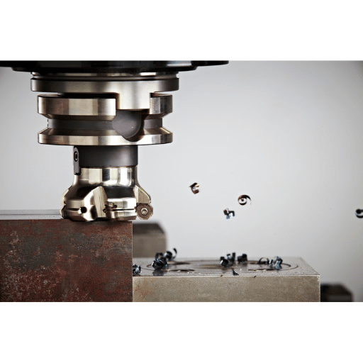
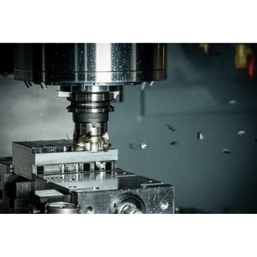
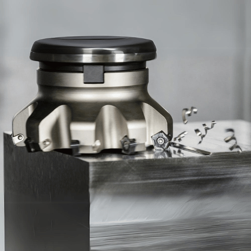
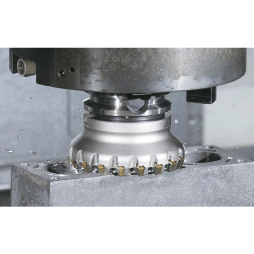
Face milling is a machining operation that uses a rotating cutter with multiple cutting edges to create flat surfaces. It is basically the face mill that is mounted to the spindle and rotates around its axis while the workpiece is fed past the cutter. The cutting edges of the tool contact the workpiece in a series of intermittent cuts to remove material from the workpiece, thus creating the desired surface flatness and finish. The face milling can be executed on horizontal and vertical machining centres. It is a highly accurate and efficient method of manufacturing operations. Manufacturers can easily tweak out the correct results by selecting the proper type of cutter and the operational parameters such as cutting speed and feed rate.
Exploring the basic face milling operation
Let me tell you as an expert, face milling is one of the commonest operations in machining. It require some key parameters to be met for the successful machining. Let’s discuss them one after the other for a clear understanding.
- Cutting Speed: The cutting speed is the speed at which the edge of the cutter travels relative to the surface of the workpiece. It tends to be the single most important factor in the quality of the cut and the life of the tool. Typically, the optimum cutting speeds range from 200 to 600 SFM (surface feet per minute). Figure 2.4. Direction and speed of a cutting tool. Carbide tools run significantly faster than highspeed steel (HSS).
- Feed Rate: How much material is being removed by the cutter per revolution, or how fast. This is a very important setting and is often mistuned. You need a reasonable feed rate to avoid overloading the tool, but not an excessive feed rate that might chew up your part. As a first guideline, try starting with 0.005 inches per tooth (IPT), and then see how things are working.
- Depth of cut: This is a measure of how deeply the cutter actually cuts the surface of the workpiece during the single pass. Make the depth of cut too shallow and you’ll be left with an excessively large cut, requiring many passes (and extra work to get the finished piece). Make the depth of cut too deep, and you will subject the tool and the machine to undue stress. The general rule of thumb for most materials is between 0.020 and 0.100 inches.
- Tool Material: The material of the cutter affects the results of the milling process. For example, carbide tools have hardness and heat resistance, which makes them good for high speed operations and harder material, while HSS tools are good for softer materials, and offer good toughness and wear resistance.
- Number of Cutting Edges: Multi-edged cutters can operate at higher material removal rates and provide improved surface characteristics as they dissipate the cutting load over several points. Four to eight edges are common for face milling cutters.
- Use coolant: Using coolant will lower the heat from milling. It will help promoto tool life and avoid overheating. water soluble coolant is usually used.
If you incorporate these parameters, and adjust as required according to your material and your cut-off conditions, you’ll do a great job on face milling. Of course, start with default settings and errors, and then fine-tune as you see fit based on real time observation and results.
Differences between face milling vs peripheral milling
As an expert in the field, I would like to explain the variations between face milling and peripheral milling, which are the two fundamental machining techniques.
1.Definition and Cutting Action:
- Face Milling: The cutting action in face milling is taking place at the end corners of milling cutter. The milling tool is plunged perpendicular to the direction of the material. The primary application of this method is to form a flat surface or to reduce the material’s height.
- In peripheral milling, however, the cutting action takes place along the circumference (ie, periphery) of the milling cutter. The tool in this case is placed parallel to the surface rather than crossing it, which makes it more suited for producing deep cuts such as slots, threads and even gear teeth.
2.Surface Finish:
- Face Milling: This is one of the most effective ways to obtain a very smooth surface finish, since the material is removed from the workpiece in a more uniform manner. The multi-edged shape of the face milling cutters associated with a larger cutting area also contributes to the consistency of the removal process.
- Peripheral Milling: Although peripheral milling can produce a fine surface finish like face milling, the surface texture is usually striations formed in the feed direction of the tool movement, which might not be as fine as that from face milling.
3.Depth of Cut:
- Face Milling: Depth of cut in face milling is usually very small, ranging from 0.020 to 0.100 inch. This amount of depth ensures that the cutter reaches through all the material and wears equally, without putting excessive stress on both the cutter and the milling machine.
- Peripheral Milling: In peripheral milling, there is deeper cut according to the length and diameter of the cutter. It is suitable for heavy material removal task.
4.Tool Positioning and Setup:
- Face Milling: The tool is set at 90 degrees to the workpiece’s surface, making it easy to set up. And working ‘face-on’ is a good position for delivering plenty of coolant, which helps keep the heat down.
- Peripheral Milling: The tool is held parallel to the workpiece in this mode, making cutter alignment critical, especially when cutting intricate shapes and deep slots.
5.Tool Wear and Lifespan:
- Face Milling: Tool wear is slower as the loads are distributed across multiple cutting edges, and longer tool life is achieved.
- Peripheral Milling: Since only a few of the cutter’s edges are constantly in touch with the material, wear can happen more quickly, requiring frequent tool changes in high‑production environments.
By understanding these differences, you will be in a better position to assign the right kind of milling in order to achieve your machining requirement. To ensure the optimisation of the process, the consideration of the requirement of material, requirement of the surface finish, depth of cut, position of the tool and the nature of the material will go a long way in making your milling process a lot easier.
The role of cutting tools in face milling
Here’s an industry insider thing I’d like to explain, from the first-person, about cutting tools and face milling. Let’s try to make it as readable as possible.
There are so many factors that go into setting up a face milling operation, especially when it comes to selecting the right cutting tool. But there are some relevant parameters that you need to look at. Let me elaborate further.
- Material of the Cutting Tool: The material of the cutting tool is very important for the performance and life of the tool. The most common materials are high speed steel (HSS) and carbide. Carbide has excellent hardness and abrasiveness, so it’s used in machining applications that require high speed.
- cutting edge: The cutting edge defines the shape, sharpness and cutting action of the drill. A sharp cutting edge will give the best finish and reduce vibrations or chatter – and careful design will minimise cutting forces, reducing tool wear.
- Coating the Tool: Coatings such as Titanium Nitride (TiN), Titanium Carbonitride (TiCN) and Aluminum Titanium Nitride (AlTiN) can improve performance by increasing the hardness, providing better heat resistance and less friction.
- Number : the number of flutes on a cutting tool can affect chip evacuation and cutting speed Face mills can have several (often five to six) cutting edges (or flutes), which are spaced such that they evenly distribute load and improve surface finish. For a given geometry, more flutes can yield finer finishes – but also may require careful chip evacuation.
- Feed Rate (also called feed per tooth): the depth to which the tool cuts into the material per rotation. For a given volume of material to be removed, the smaller the cutting edge, the higher the feed rate required; however, higher feed rates could lead to increased wear on the tool and surface roughness;Tool life and surface finish: two conflicting factors to consider.Cutting Speed (also called surface speed): the speed at which the tool cuts into the material.
- Apply Coolant: Coolant application is important for face milling to prevent overheating and prolong the cutting tool’s lifespan. The coolant reduces thermal deformation of workpiece and the tool to maintain higher dimensional accuracy and surface quality.
You can only do this if you consider these parameters correctly when you choose a cutting tool for your face milling operation. When selecting your cutting tool keep in mind that you want to remove material by chipping, that this chip should be long and slender, that the chip thickness should be thin, and that you want to do all this as fast and accurately as possible and with as little wear to the tool as possible. Happy milling!
Choosing the Right Tool for Face Milling
Choosing the face milling tool as per your machining requirements is a combined effect of the material with desired surface finish at right machining parameters of feed, speed and flushing. With the thrust on industry and growing demand of tools in production, it is always important to choose the right tools for the right job. Hence, the finish/indentation depends upon the geometry of the tool, in particular, shape of the cutting edge and number of flutes. Balancing the cutting forces, the tool life and the chip Evacuation becomes prime to get the best result in face milling and engages to select the right carbide grade. And when ti-nitride coating are used on Carbide, the balanced result with lesser wear can be obtained. The use of titanium nitride (TiN), titanium carbon nitride (TiCN), and aluminium titanium nitride (AlTiN) coating on the face milling tools not only improves wear resistance but also heat resistance with the help of their hardness to reduce the heat generated in the metal cutting zone and thus reducing the friction.
Comparing milling cutters and inserts for optimal performance
I’ve found with milling cutters and inserts that the trick for getting the best performance is to understand and balance a number of parameters. I’ll go through what goes into my consideration step by step and in detail.
- Material considering: The first thing I look at is the material to ‘mill’ from. Different materials require different types and grades of cutters – say you have to mill steel, versus aluminum or titanium – or even different grades of the same material. Titanium, for example, cuts better with carbide inserts due to its hardness factor.
- Cutter Geometry: First, the geometry of the cutter itself has a huge effect on performance. I look at the design of the cutting edge, things like whether it has positive or negative rake angle, because that has an effect on the cutting forces and on the flow of the chip. Generally, positive rake angles give a smoother cutting action. They are easier on the machine.
- Number of Flutes: The fewer the flutes on a cutter, the more chip evacuation issues and surface finish problems you’ll have. Conversely, the more flutes, the more you can do to get a really fine finish, but you can also have more difficulty evacuating chips. I generally try to match the number of flutes in the tool to the work: fewer flutes for roughing, more for finishing.
- Coating Technology: Titanium Nitride (TiN), Titanium Carbonitride (TiCN), and Aluminium Titanium Nitride (AlTiN) coatings on tools improve its performance drastically, as they increase heat resistance and lower unwanted friction. This combination boosts tool life and provides better surface characteristics.
- Cutting speed and feed rate: These two parameters are also dependent on the cutter you choose as well as the particular insert you are using. The higher the cutting speed, the better the productivity of the machine but the higher the wear on the tool (the insert). I start with the setting that the manufacturer recommends in the catalog, and then I adjust more precisely after I run the program and take a look at the result.
- To apply Coolant: The main part of my job is to make sure that I am using coolant effectively, which is very important to reduce the amount of heat, and help me wear my cutting tool longer. I can reduce thermal deformation, be more accurate on the dimension and having a better surface texture, if the coolant is used in the right way. for example, the high pressure coolant system.
When I examine them individually, I can optimise my tool selection for the unique parameters of each face milling operation. This way, I will maximise the accuracy and longevity of my tool, while still producing the fastest, most economical cuts.
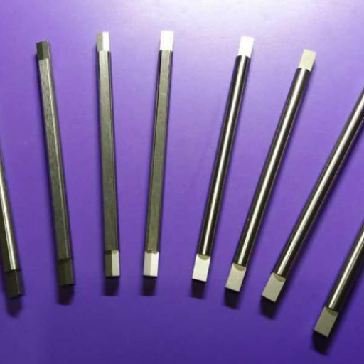
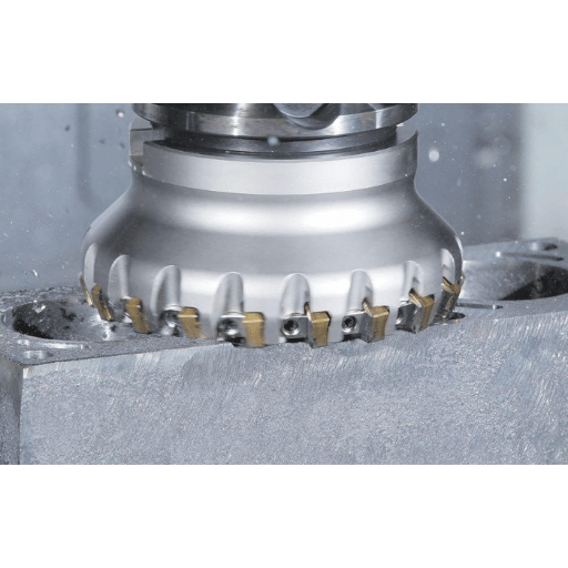
Types of face milling cutters
With more than 25 years in the industry, I provided some insights into the several kinds of face milling cutters, their range, difference, and advantages in machining. This will give you a picture about what each kind is best for; enabling you select the appropriate tool to the machining task, and in turn providing optimal results and efficiency.
- Stock Face Mills: These cutters are the most versatile and widely used and have many cutting edges. They are excellent for removing large amounts of material quickly, which makes them good for roughing operations. The quantity of inserts can vary, and you can balance your result between quantity of chip removal and surface finish.
- Shell Mills: Shell mills are more versatile for applications as they can adapt to different cutting situations through replacement of the inserts or changing other parameters. They are particularly adapted to more aggressive applications such as heavy cutting and high volume material removal.
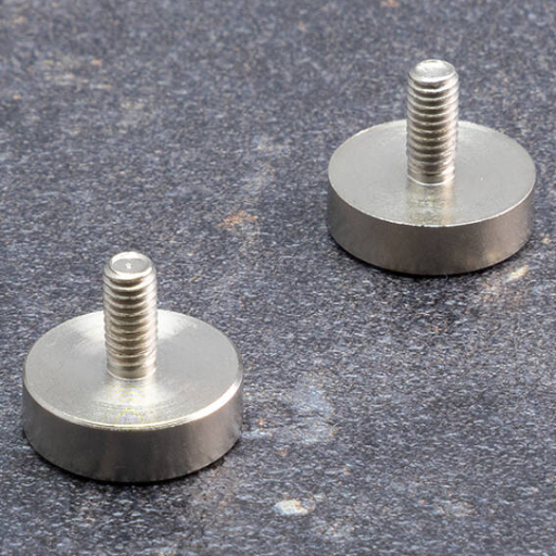
- Replaceable Face Mills: These cutter inserts are replaceable which can reduce cost when worn inserts are replaced rather than replacing the entire tool. These are good for high speed spindle operations and tough to machine materials such as stainless steel and titanium.
- Indexable Face Mills: These uses indexable inserts which are then rotated to expose a fresh cutting edge providing more consistent performance and reduced downtime. These are extremely effective before replacing them for a more extended period.
- Angle Face Mills: They have angled inserts and are used to set cutting angles. They are ideal when you are dealing with unusual geometries or have specific contours you want to achieve.
Once you understand these different varieties, you’ll be able to better determine the face mill that works best for you in terms of improved material removal rates, cost savings through insert replacements, or specialised cutting requirements.
Understanding the importance of cutter angles and cutting speed
As a machining professional, it is very important for you to understand how machining parameters such as cutter angles and cutting speed influence machining process. Your machining process will have a significant influence on its effectiveness and efficiency.
Let us examine, in detail, how your machining parameter influence your process.
1.Cutter Angles:
- Rake Angle: The angle between the face of the cutting tool and the work surface perpendicular to the active cutting edge. Positive rake angle reduces cutting forces and requires less power, while a negative rake angle is more robust and required for hard materials but requires more power.
- Relief Angle: This angle helps in preventing the tool from rubbing against the workpiece. It also helps in reducing the wear and tear of the tool and also in giving the tool a smoother finish. A variety of angles are used in relief depending upon the nature of the material to be cut, and the desired finish.
- Lead Angle: The angle between the cutting edge and the workpiece surface. A larger lead angle dissipates the cutting load over a larger area, reducing tool wear and improving surface finish, but is less useful for very tight tolerance work.
2.Cutting Speed:
- Surface Footage per Minute (SFM): Proper SFM changes according to the material of the tool and the material of the workpiece. Speeding up results in shorter times of production but in the reduction of tool life, while decrease of speed causes the extension of tool longevity but will reduce the material removal rate.
- Feed Rate: This is the rate at which the cutter moves into the workpiece. Calculations are expressed in inches per tooth (IPT). The appropriate feed rates allow the chip to be removed effectively and the heat generation in the cutting process to be controlled.
- Spindle Speed (RPM): The speed of the spindle is the key to efficient cutting. Higher RPMs are used for smaller diameter cutters. Lower RPMs are used for larger cuts.
Knowing these parameters in their depths enables you to establish optimal cutting conditions, longer tool life, better surface finish, and ultimately, successful machining operations. Each of these parameters deeply affect your workflow, so you are able to get the job done right.
Optimizing CNC Machining with Advanced Face Milling Techniques
The author is an expert in CNC machining. Optimising CNC machining of complex parts with face milling usually involves balancing many parameters to achieve high efficiency and precision. The first step is to identify the material of the workpiece and choose an appropriate cutting tool material and geometry. For example, the relief and lead angles should be selected carefully so that material removal can be carried out safely while maintaining a good surface finish.
Furthermore, proper selection of cutting speed, feed rate and spindle speed are critical. All of these varied parameters need to be precisely calculated depending on the particular workpiece and its intended result. Raising the surface footage per minute (SFM) of the cut and optimising spindle speeds can increase productivity, but need to be controlled in order to prevent premature tool wear. On the other hand, operating at lower speeds and maintaining control of the feed rates will increase tool longevity and better surface finishes – arguably, at the cost of throughput.
In addition to this, further optimisation can be achieved by deploying highly advanced simulation and monitoring tools. These can perform predictive maintenance and adjustments in real time to prevent breakdowns and maintain optimal machining operations throughout. In all, the synergy between theory and practice allows for the optimisation of CNC machining processes and the production of precision mechanical parts with superior quality while also achieving a significant reduction in production costs.
High feed milling vs general face milling strategies
For those who are not familiar with both the high feed milling and general face milling strategies, it may be interesting to compare the differences between these two methods.
1.High Feed Milling:
- Cutting Speed: High feed milling operates at high cutting speeds. This is because it aims at material removal at high rates.
- Feed Rate: Since the feed rate in high feed milling is much higher (double or even triple as shown below), we can do the same on a smaller scale in a shorter amount of time.
- Depth of cut: Since the load on the cutting edge must usually be very low in high feed milling, the depth of cut will be shallow. Feeds and speeds will consequently run at high values.
- Tool path: High feed milling is a type of tool path that prioritises feed-rate stability over path stability and accuracy.
- Application: Ideal for roughing operations where removing large volumes of material rapidly takes precedence over surface finish.
2.General Face Milling:
- Cutting Speed: General face milling uses moderate cutting speeds, which are tuned to the material and finish requirements.
- Feed rate: it is lower than in high feed milling, which can prolong tool life and realise a fine surface finish.
- Depth of Cut: Generally face milling has deeper cuts than high feed milling, which maximises material removal per pass.
- Roughing Path and Finishing Path: Tool path is designed for stable and accurate machining and has a prominent feature of both roughing and finishing.
- Application: Used in the final phases when the workpiece surface quality and dimensional tolerances must be precise.
The main point of the comparison is that high feed milling is best when you need to work fast and remove more material at a time without considering the surface finish and accuracy. And for more general face milling, it is best to balance your feeds per tooth to match the material you need to remove with the surface finish or accuracy you require for your project. This will help you determine which strategy suits your machining operations.
Benefits of using wiper inserts for surface finish improvement
Wiper inserts can be used to increase the surface finish of the parts during machining operations. The following are the main advantages of using wiper inserts:
- Better Surface Finish: Specific geometry of wiper inserts smooths surface while cutting, achieving better surface finish compared to standard inserts. This is useful in applications where surface quality is critical.
- Higher Feed Rates: As a result of providing a smoother finish, wiper inserts allow you to machine at higher feed rates without compromising the surface quality. This translates to increased productivity, as you can remove more material in less time.
- Decreased Tool Wear: The broad width of the inserts provides a more even distribution of the cutting forces along the cutting edge, which decreases stress on the cutting edge. This can result in a prolonged cutting edge life and decreased tooling costs.
- Consistency of Surface Quality: Wiper inserts continually help to keep surface finish constant across the entire workpiece. This enables processes such as aerospace and automotive manufacturing, which require uniformity.
- Versatility Across Materials: Wiper inserts work on everything from soft aluminiums to hard steels.
- Less secondary operations: high-quality finishing in the first pass of wiper insert sometimes allow us to eliminate some secondary finishing operations, which saves time and man-hours.
In conclustion, wiper inserts will help to finish the surface, increase feed rate, decrease tool wear, ensure consistency, offer a wide range of machining options, and eliminate any additional finishing steps. As such, they are a great option to improve your machining efficiency and quality.
Heavy duty face milling for large amounts of material removal
Developed to machine large amounts of material in a short period of time, heavy-duty face milling allows machinists to create a large number of flat surfaces faster than using other methods. It is particularly useful for aerospace, automotive and heavy machinery industries where large volumes of metal must be shaped for rapid production of large parts.
With my years of experience working in your industry, I can address some commonly asked questions about heavy duty face milling:
1. What is heavy duty face milling?
In heavy duty face milling, a wide flat cutting tool (the face mill) is used to remove large quantities of material from the work in multiples passes. On each pass, a large slice of material is removed and a suitable shape is generated from the work.
2. What types of materials can be processed with heavy duty face milling?
Heavy duty face milling is well suited to cut a wide variety of materials, including:
- Aluminum and other non-ferrous metals
- Mild steels and stainless steels
- Cast iron
- High-strength alloys
3. What parameters should be considered for optimal results?
To ensure that heavy duty face milling runs at its best, a couple of dozen parameters have to be set:
- Cutting Speed (Vc): Speed at which the cutting edge is moving through the material (typical units in metres per minute, m/min). Starts with a unit value and must then be reduced for the hardness of the material and the capacity of the tool.
- Feed Rate (fz): It is the distance the tool advances in a single revolution of the spindle. It is measured in millimetres per tooth (mm/tooth) and is higher in heavy duty applications (ie, higher numbers) since they reduce the machining time.
- Depth of Cut (ap): This is the vertical distance the cutting tool removes material in one pass, stated in millimeters (mm). In heavy-duty operations, a high-depth of cut can be used to maximise material removal rates.
- Use coolant: Coolant will prolong tool life and improve surface finish. It’s especially important with high-strength materials.
4. What are the benefits of heavy duty face milling?
Heavy duty face milling offers several advantages:
- Efficiency: Rapid material removal rates mean shorter machining times and higher productivity.
- Cost-effectiveness: Efficient material removal and longer tool life can lower overall production costs.
- Precision: Modern face milling tools and techniques can hold tight tolerances and high surface finishes, even in high material-removal situations.
5. How can tool wear be managed during heavy duty face milling?
Wear is a major issue during heavy duty operations, here’s how we could mitigate it:
– Paraphrase
- Choosing a material for the cutting tool: You could go for carbide – because it is hard-wearing and resistant to the heat.
- Parameter optimisation: Cutting speed, feed rate and depth of cut must be adjusted in line with wear.
- Constant monitoring and replacement: Keeping an eye on the condition of the tool and replacing inserts as needed keeps the performance consistent.
By having a clear grasp on each of these limitations and employing the appropriate method under the right circumstances, heavy duty face milling can emerge as one of the most effective and efficient treatment in heavy metal removal in a wide range of industrial procedures.
Overcoming Common Challenges in Face Milling Operations
Face milling operations (as with most other general-purpose cutting processes) can have a number of pitfalls to overcome, particularly when using larger tools in heavier-duty applications. So here’s a brief response to some of the common questions that I am asked:
Material Hardness: Harder materials mean more wear on your tools and the need for more robust tooling solutions. High-quality carbide inserts with a correct cutting parameters are the solution here.
Vibration and chatter: these can affect surface finish and tool life. Use vibration-damping tool holders, change cutting speeds, etc to reduce these problems.
Heat Generation: Too much heat can cause tool failure and softer surface finishes. Proper coolant regimens and higher heat-resistant tooling can solve this problem.
Tolerances: Close tolerances call for delivering consistently correct milling performances. Machines have to be well calibrated, and tools as well as cutting parameters have to be adjusted to the application.
By tackling these issues using the right approach, face milling operations can be made more productive, generate better surface quality, and allow tool life to be extended.
Addressing issues related to milling cutter wear and failure
Addressing issues of milling cutter wear and failure is essential to maintaining an efficient, productive machining process. Here is a comprehensive write-up that explains how to deal with it:
Material Hardness: Milling softer material extends the tool life. Use high-quality carbide inserts for heavier cuts and better life. The parameters include:
- Cutting Speed (Vc): Lower cutting speeds can reduce the rate of tool wear.
- Feed Rate (Fz): Adjusting the feed rate ensures optimal cutting and tool life.
- Depth of Cut (Ap): The lower the depth of cut, the less the load on the milling cutter.
Vibration and Chatter: Vibration and chatter can deteriorate surface finish and tool life. The following parameters should minimise those issues:
- Tool Holder Damping: Using vibration-damping tool holders helps absorb excess vibration.
- Cutting Speed: Adjusting cutting speeds can help find a sweet spot that minimizes vibrations.
- Tool Path Strategy: Tool paths that minimize the number of sharp changes in direction (such as pauses before the next move) will leave less of a gap in engagement with the material.
Heating of Tool or Workpiece: Intense heating will cause damage to the tool and the workpiece, and is, therefore, to be avoided. Keep some points in mind for this purpose.
- Coolant Usage: Employing an effective coolant strategy helps dissipate heat efficiently.
- Cutting Tool Material: The materials with a higher heat-resistant property get better performance by the tool working on high-temperature condition.
- Cutting Parameters: Lowering cutting speeds and feed rates can reduce heat generation during milling.
Keeping Tolerances: In high-precision applications, keep the following parameters close. Key parameters to keep include:
- Machine Calibration: Regularly calibrate your milling machines to ensure accuracy.
- Tool Quality: Use high-quality tools that are routinely inspected and maintained.
- Optimise Number of cuts: Another element of design is to optimise the number of cuts within a tolerance. This can be achieved by selecting the most precise cutting parameters, including speed, feed, and depth.
Carefully and effectively controlling at least some of these parameters can mitigate milling cutter wear and failure, improve tool life and provide better finishes in face milling.
Strategies for managing cutting forces and vibrations
It is important to keep the cutting forces and the level of vibrations to a minimum to avoid damaging the workpiece and to facilitate efficient milling. Here are a few rules of thumb on how to do that.
- Tool Selection: Choose the best tool you can. High-quality tools with proper shapes, such as geometrical forms of the cutting edges, can greatly reduce cutting forces and vibrations. Tools with shorter overhang, for example, can minimise deflection and increase stability.
- Feed rates: Another way to mitigate cutting forces is to change the feed rates. If you lower feed rates, you can reduce cutting forces, but you must be careful not to lower it too much or your productivity will suffer. Try decreasing your feed per tooth and see if that is sufficient for your application.
- Slow Speeds: Like the feed rate, speed controls often matter greatly. Higher speeds can amplify vibrations, while lower speeds can be more controllable. Monitoring the speed and slowing down can make all the difference.
- Tool Holding: Handle carefully, it is one of the major vibration cause. Use high-quality tool holders, collets, chucks, etc can provide the tools with a more firm grasp, preventing tool deflection and vibration.
- Path Cutting Strategies: The type of path your tool takes can also contribute to vibrations. Choose smoother, more continuous tool paths, and avoid tool paths that have abrupt ‘jumps’ when going from one location to the next. This will keep your tool engaged with the material in a more stable manner.
- Staggered Tooth Cutters: In some materials and applications, use of a staggered tooth cutter helps to spread the cutting forces more uniformly and reduce vibrations.
- Material Holding: To ensure the stability of the component, the correct clamping of the holding part is necessary. Loose or wrong clamping can cause excessive vibrations. Check the clamping setup to check the stability.
- Damping Systems: Damping technologies, such as using a tuned mass dampers (TMD) or active damping systems, could absorb or counteract vibrations and help smooth the milling process.
With just those two parameters, you can control cutting forces and vibrations to optimise milling.
Tips for maintaining optimal spindle speed and feed rate
As someone who works in the industry, I’ll give you some practical advice for maintaining spindle speed and feed rate parametres, which is critical for the best output in the process of milling for you. Here goes the breakdown; I hope it helps?
- Material properties: All materials respond differently to cutting. Soft materials (such as aluminium) require higher spindle speeds and feeds, while hard materials (such as steel) require lower spindle speeds and feeds. So, the nature of the material you’re machining is the first thing you need to know.
- Tool Material: Tool type also impacts the best possible spindle speed and feed rate; HSS tools in general can run faster than carbide (always refer to your tool’s manufacturer recommendations).
- Diameter: The diameter of your cutting tool will help to determine your speed and feed settings, too. Larger diameter tools should run at lower speeds than smaller diameter tools in order to decrease vibration and improve surface finish.
- Depth of Cut: The depth of the cut, in other words how much the tool penetrates the material, affects both spindle speed and feed rate. Deeper cuts will normally have lower speeds to avoid breakage of the tool and also to prevent chatter and vibration in the milling process.
- Workpiece Stability: Ensure your workpiece is not moving, or vibrating by re-clamping your workpiece.
- Tool Condition: New tools run better than worn ones, and sharp, well-maintained tools are able to run at much higher speeds and feed rates. Like a good set of chef’s knives, you get a much better cut with a sharp chisel or relief cutter. All tools deteriorate with time, so regularly inspect and maintain.
- Coolant Use: a sudden change in coolant use can have a dramatic effect on your spindle speed and feed rate. Because coolant removes heat, you’ll be able to run your tools faster without the risk of overheating.
- Machine Stiffness: When a machine exhibits a higher degree of stiffness, it gives you more power to work with. You will be able to run at faster RPM and IPM (inches per minute) during your operation without sacrificing quality or accuracy.
This way, when you follow these tips and adjust those parameters properly, you successfully maintain the optimal spindle speed and feed rate and get an efficient, qualitative milling.
Exploring the Different Types and Uses of Face Milling Machines
To suit the varied machining requirements, different types of face milling machines have been designed. Horizontal Face Milling Machines are designed specifically for heavy-duty milling operations. The most important feature of this machine is the ability to remove a large quantity of material in a short time. They perform best to create flat surfaces on large workpieces. Vertical Face Milling Machine, on the other hand, is designed to function both in roughing and finishing operations. They are best suited for applications that require the highest degree of accuracy and finish. These machines are normally used for finishing operations, where the working conditions demand tighter tolerances and finish.
Various industries use face milling machines for different purposes. To name a few, automotive face milling machines are employed to make engine blocks and others. Face milling machines play a major role in manufacturing the complex parts of an airplane found in the aerospace industry. Face milling machines are also used in manufacturing molds and dies, which requires the machine to perform accurate cuts and deliver a desired surface finish. Since different applications have different requirements, selecting the right type of face milling machine and leveraging its particular advantages can help manufacturers to enhance performance, optimise machining, obtain the required surface finish, and improve overall product quality.
From vertical to horizontal CNC milling setups
To adapt, it’s important to have a clear understanding of what each vertical or horizontal CNC milling setup offers, in addition to knowledge of which applications are ideal for each option. Here are the key parameters to keep in mind:
1.Workpiece Geometry:
- Vertical CNC Milling: Workpiece with flat or irregular surface area, where gravitational force aids in workpiece stability.
- Horizontal CNC Milling: Better for complex geometries and larger workpieces which might need more than one side of a part machined without having to re-position it.
2.Material Removal Rate (MRR):
- Vertical CNC Milling: good for light to medium MRR (material removal rate), which makes it a good choice for fine-detail work and finishing operation.
- Horizontal CNC Milling: more aggressive material removal tasks are possible because of better chip evacuation, leading to the possibility of higher MRR.
3.Chip Management:
- Chips tend to gather in the area close to the vertical CNC milling, which need to be cleaned up more often.
- Horizontal CNC Milling – Chips fall due to gravity making it easier for them to be removed. This improves the machine’s efficiency by decreasing the amount of time the part being milled has contact with the cutting tool, and prevents it from being recut. This in turn increases the life of the tool.
4.Tool Access and Machining Flexibility:
- Vertical CNC Milling: Easier for operators to feed in stock and change the tools, but less versatile for multi-sided machining.
- Horizontal CNC Milling: Provides better access for tools to reach multiple sides of the workpiece without repositioning, increasing productivity on parts with many sides.
5.Footprint and Space Considerations:
- Vertical CNC Milling: Small footprint, ideal for limited space environments.
- HORIZONTAL CNC MILLING: Takes up more floor space, but it can work on bigger and more varied pieces of workpieces.
These variables enable makers to decide upon the most appropriate milling setup for manufacturing purposes. In conclusion, while vertical CNC milling is good for precision and small parts, horizontal CNC milling is a better option for large, complex parts due to superior efficiency and flexibility.
The capabilities and limitations of face milling machines
As an expert in the field,I’ll discuss the features and limitations of face milling machine in a simple and easy to understand language. So,lets take a look at the parameters of face milling machine, which are widely used in mass production lines.Here, I will detailedly describe its key parameters.
1.Material Removal Rate (MRR):
- Capabilities:Face milling machines are capable of removing a lot of material in a short amount of time. They are good to consistently effective in producing a flat surface on steel, aluminium, cast iron or other materials.
- Shortcomings: They are big for smaller surfaces, and face milling machines might not be as precise as more exact milling types for very fine or intricate details.
2.Surface Finish Quality:
- Capabilities: Because face milling machines offer a superior surface finish, they are often employed on the last operation of a part, when you want it to look like a gleaming new toy.
- Limitations: Achieving this level of surface finish may require additional finishing steps such as grinding or polishing.
3.Flexibility and Versatility:
- Capabilities: The machines are highly versatile and able to process a variety of cutting tools and setups. They are best suited for all operations including roughing and finishing.
- Limitations: Complex geometries can sometimes limit the flexibility/agility of the machine as accessibility of certain locations to the cutting tool can be limited by the configuration of the machine.
4.Tool Life and Cost:
- Capabilities: By spreading the wear evenly over the entire face of the tool, face milling machines tend to significantly increase tool life. This in turn reduces the total amount of time spent changing tools, saving time and increasing efficiency.
- Disadvantages: Setup cost is higher initially and costs of high-quality cutting tools are higher than in other milling.
5.Workpiece Size and Shape:
- Capabilities: Where they really shine is in larger, flatter surfaces and are more equipped to work with heavy workpieces and not slow down.
- Limitations: These machines aren’t well-suited for smaller, delicate workpieces or parts that need to be positioned and re-positioned.
6.Chip Management:
- Capacities: Face milling machines with adequate chip evacuation can remove lot of material without choking.
- Drawbacks: If chips are not handled efficiently, for example with a chisel or spanner, a recutting of the chips can result in a decrease of surface quality and tool life.
This will help the manufacturer to comprehend the core capabilities and shortcomings of it, and to decide if a face milling machine is the right fit for their production consideration.
How to choose the best milling machine for your specific milling tasks
As an expert in the field, I am of the moment to assist you in choosing the most suitable milling machine perfectly meets your needs.When choosing a new milling machine, there are several important parameters you need to take into consideration.
1.Type of Material:
- Consideration: Different materials have varying hardness and properties.
- Answer: For softer material like aluminium, a machine with lower power is suitable. For hard material steel, a machine with higher power and stiffer is required.
2.Precision and Tolerances:
- Consideration: Determine the level of precision your task requires.
- Explanation: We will use a CNC milling machine which has a high precision and making of delicate parts.
3.Workpiece Size and Shape:
- Consideration: Assess the dimensions and geometry of the workpieces you’ll be milling.
- Explanation: In order to machine a bigger piece, the working envelope of the machine needs to be bigger. To machine an intricate shape, a multi-axis machine might be needed.
4.Production Volume:
- Consideration: Gauge the volume of parts you need to produce.
- Answer: For small volumes, it may be better to stick with a manual, or semi-automated machine, which would still yield a high return on investment.
5.Tooling Requirements:
- Consideration: Identify the types of tools you will need for your milling tasks.
- Instruction: You must also ensure that the machine is compatible with the actual type of tools you require to perform your tasks. Certain operations might necessitate special cutters or end mills.
6.Budget:
- Consideration: Determine your budget constraints.
- Explanation: Weigh the initial cost against the long-term benefit. A high-capacity machine may be costlier in terms of the initial purchase, but will likely save money in the long run.
7.Flexibility and Expandability:
- Consideration: Plan for future needs and potential changes in your production line.
- Explanation: Opt for a machine that can be upgraded or changed to suit upcoming jobs but still rely on the same investment already made.
If you carefully choose your parameters you might conclude that a milling machine will ‘work’ for you, in the sense of yielding an optimal combination of production capability and cost within the constraints of your financial resources and needs. This is the level of reasoned contemplation we hope to see among new customers, as we’re certain it would bear fruit.
Reference sources
- Online Article: Modern Machine Shop – “Face Milling: Efficient Machining of Large Surfaces”
-
- Summary: This article provides a comprehensive overview of face milling, focusing on techniques to improve efficiency in machining larger surfaces. It discusses various strategies, tool selections, and machine settings that enhance machining accuracy and productivity. The article is authored by industry professionals with expertise in machining operations, making it a credible source for practical insights.
- Academic Journal: Journal of Manufacturing Processes – “Optimization of Face Milling Process Parameters Using Response Surface Methodology”
- Summary: This peer-reviewed journal paper explores the optimization of face milling process parameters to improve surface finish quality and minimize tool wear. Utilizing response surface methodology (RSM), the study provides empirical data and analysis techniques relevant to both researchers and practitioners interested in honing their face milling processes. Its scientific rigor and detailed methodology make it a reliable source for academic and applied research.
- Manufacturer Website: Sandvik Coromant – “Face Milling Tools and Techniques”
- Summary: Sandvik Coromant’s website offers a detailed guide on face milling tools and techniques. The content covers the selection of appropriate cutting tools, setup procedures, and troubleshooting methods to achieve optimal results. As a leading manufacturer in the cutting tool industry, Sandvik Coromant provides accredited and well-researched information, making this an authoritative source for both novice and experienced machinists.
By reviewing these sources, readers can gain a solid understanding of face milling processes, from theoretical foundations to practical applications in an industrial setting.
Frequently Asked Questions (FAQs)
1. What is face milling?
Face milling is a machining process where the cutting tool’s axis is perpendicular to the surface of the workpiece. It primarily involves removing material from the face of the workpiece to create a flat surface. This process is widely used in manufacturing to achieve high-quality finishes and precise dimensional tolerances.
2. What are the main parameters involved in face milling?
The main parameters in face milling include cutting speed, feed rate, depth of cut, and the type of cutting tool used. Optimizing these parameters helps enhance surface quality, increase tool life, and improve overall efficiency of the milling process.
3. How can I optimize face milling process parameters?
Optimization can be achieved through empirical methods like Response Surface Methodology (RSM), as well as practical experience and adjustments. Utilizing specialized software and referencing scientific research, such as academic journals and industry standards, can also aid in fine-tuning process parameters for optimal performance.
4. What types of tools are used in face milling?
Face milling utilizes a variety of cutting tools, including carbide inserts, high-speed steel (HSS) cutters, and coated tools. The choice of tool depends on the material being machined, the required surface finish, and the specific milling machine capabilities.
5. How does the surface quality of the workpiece affect the selection of face milling tools?
Surface quality requirements dictate the choice of cutting tools, their geometry, and the machining parameters. For example, achieving a smooth finish may require tools with finer teeth and precise control over the feed rate and depth of cut. Conversely, roughing operations may utilize tools designed for rapid material removal with less emphasis on finish quality.