
CNC machining drawings include very essential objectives, which involve making accurate elements from scratch. As technical drawings, these drawings define several specifications which include size, tolerances, and materials through which the manufacturer is able to produce quality products. Knowing how to read and understand CNC machining drawings promotes interaction between machine operators and designers and helps minimize risks concerning end item specifications. In this article, we will discuss the most important components of CNC machining drawings, their types, and the ways of how not to design so that the reader gets a complete idea of this crucial area of step by step equipment development.
What are Technical Drawings for CNC Machining?
cnc machining drawing
As for the technical drawings for CNC machining, they can also be defined as the diagrams that explain the manner in which a certain part ought to be manufactured on a CNC machine. As per what I have seen, these drawings are accompanied with important information such as views, dimensions, tolerances, surface finishes and specifications for the materials used. These two drawings are critical in relieving the confusion that may be existing in regards to the requirements needed to start the work by the fabrication team. These two cannot be used in the usual sense, the technical drawing ut, least and language which these guides are meant to illustrate eliminate the misunderstandings accurate and wording as well hoopla says. To begin most of this information is contained in the traditional manuals and drawings and really the amount of explanatory notes commands to extreme. The professional and technical drawings capture not only the creative aspect of the exercise but also the illustrating the practical functionality with which it is designed to perform.
Introduction to Technical Drawings and Their Composition
From what I have read in the firstmilled websites on technical drawing for CNC machining, I realize that these technical drawings are very important in the management of manufacturing processes as they act as blueprints to these production systems. They are a visual representation of the design but also bring out other technical aspects such as measurement, tolerances’ limits, and surface finish. Dimensioning is the process of defining the magnitude of some features while tolerance describes how much deviation is allowed from the actual measurements so that the parts can be assembled.
Other factors that were emphasized, and I believe are necessary to include are:
- Dimensions – These shall be legibly and accurately shown proportioning the dimensions and positions of various features on the piece.
- Tolerances – provisioning for risk where some dimes will be in excess or deficit from the limits provided.
- Surface Finish Specifications – The value added to the article consists of a surface that adheres to a certain specification regarding roughness and smoothness and is represented with a standard sign.
- Material Specifications—These explain the places of use of certain materials in the engineering process, ensuring that the necessary properties required in the end use are achieved.
Such features not only facilitate comprehension but also lessens confusion between the designers and machinists, closing the gap between the idea and the end result.
Importance of Technical Drawings in CNC Machining Process
My analysis of the most popular sources of information on technical drawings in CNC machining from top-ranking sites in Google reveals that such drawings are crucial in the manufacturing process. Not only do they help achieve accurate production, but they also foster effective interactions between engineers, designers, and machinists. The assessment of engineering and production drawing’s importance is emphasized as it ensures that all parties understand what is required for any form of machining.
For instance, critical technical parameters include the following;
- Dimensions: Well outlined measurements enhance the fabrication of each component to the required design specifications to eliminate prevailing costs associated with mistakes and reworks.
- Tolerances: Tolerancing sets acceptable limits of variation, making it possible for some elements of the parts to be correctly aligned while ensuring that the assembly can still maintain proper function.
- Surface finish specifications: These details guarantee that the cosmetic product performs its functional purpose in one way or another, providing finishing touches or proper fitting in and carrying out its intended purposes.
- Material specifications: Clearly defining the suitable materials to use ensures that the end result meets the required strength, durability, and other performance properties.
Considering these parameters, the technical drawings may be considered an elementary building block to enable successful and well-ordered CNC machining processes, resulting in better end product quality control and reliability.
Types of Technical Drawings Used in CNC
CNC technical drawings are an important topic as can be seen from my findings from consulting the ten best websites on the subject. It was possible to differentiate several various drawings for CNC machining which are significant for ensuring good manufacturing and high efficiency. Each type has a specific function and is highly related to the technical parameters mentioned before. Here are the main types I identified:
- Detail Drawings: These include pictorial or descriptive views of a part, normally referring only to the construction details such as sizes and tolerances. They are vital documents that contain manufacturing appeals in every detail of the parts constructions ever made to meet the necessary requirements of the parts.
- Assembly Drawings: These show how parts of different parts are assembled into a complete unit. They focus on parts’ relationships and functions to achieve a common goal of making sure all the parts manufactured are in place and work properly.
- Machining Drawings: These, on the other hand, are more concerned with the processes that are to be done. These drawings portray the cutting paths and the tools that are required. For everything to cut properly according to the surface finishes required and the tolerances specified, these drawings are highly significant for the machinists.
- Fabrication Drawings: These drawings are mainly aimed at assembly work involving welding or other fabrication processes. They include the types of joints that ought to be used, the size of the welds, and the materials to be used.
- Schematic Drawings: These drawings are not prevalent in traditional CNC machining. However, they summarize the electrical and hydraulic systems necessary for an automated process. They guarantee that codes concerning the proper working of CNC machines are followed and include things like operating tolerances.
To conclude, every technical drawing has a role to play in the CNC machining process by elaborating technical suggestions, enhancing the exchange of information on the precise specifications of the final glaze, and maintaining the accuracy and quality of the finished product.
How is a Design Ready for CNC Run in Steps Made?
For every part that has to be machined I make a technical drawing where I define said part’s dimensions and tolerances with the approach that best meets functional requirements. appropriate software is utilized to produce very detailed 2 dimensional or 3 dimensional designs that represent geometric features and critical information such as surface finishes and the materials to be used. In this stage, I also incorporate all necessary assembly and machining details in the drawing with cutting paths and tool types specified. It is also equally important to ensure that the drawings have been done according to relevant industry standards, which helps communication with machinists and all quality expectations with regards to the finished product are met. For all technical drawings, my last point is that I have to check them in detail, preferably with some of my coworkers for cross-checking right before we hand over our work to the making department.
Steps to Make an Impressive Technical Drawing
- Research and Define Requirements: When researching project requirements, I start with project-related information available from credible sources to understand the industry standards. This helps ensure that the drawing will meet the requirements in terms of content.
- Select Appropriate Software: In this case, I have to select the specific CAD software that will assist in creating the comprehensive drawings. In place of these two, AutoCAD and SolidWorks are examples of CAD tools that focus on 2D drawings and 3D modelling, respectively, and have been utilized extensively for precision drawings.
- Draw Basic Geometry: I begin by generating the basic geometric shapes from which the part is defined. This involves correctly assigning the dimensions of parts in terms of their length, width, height, and even angles.
- Incorporate Tolerances: I am also careful to insert such drawing tolerances into my drawing. These are common tolerances of ranges, and they include about plus or minus 0.01mm for precision parts and 0.5mm for less critical purposes for the tamp where the function of the part and the production process can be justified.
- Add Material Specifications: I identify and specify the material specifications for the part. For instance, using material codes hinged on ASTM A36 for structural steel or 6061-T6 for aluminium serves to identify the required material properties.
- Detail Assembly Instructions: I also give detailed assembly instructions, including the order of assembly and the tools required if the part is to be fitted into an assembly. This helps avoid dislodgement of parts during production.
- Include Surface Finish Annotations: Finally, I detail the surface finishes to be used, including values averaged over an area of roughness like Ra, which is measured from 0.8 micrometers for the machined surface to four micrometers for the rough surface. This ensures the part is functional and pleasing to the eye.
- Verify Against Standards: In the final step, I ensure that the final drawing meets industry standards, such as ASME Y14.5, which covers standards and practices for geometric dimensioning and tolerancing, also known as Gis.
- Collaborate for Feedback: I take time to work with peers or supervisors before I finalize any case to seek their opinions. Their opinions are useful since they can help point out any possible problems or enhancements.
- Finalize and Submit: Lastly, I ensure that all documents, including the technical drawing to be done, are checked carefully for accuracy so that all parameters can be represented and defended in the drawing and submitted for manufacturing.
Employing technical drawing
A few fundamental elements must be considered when preparing a technical drawing to guarantee that all the required information is presented adequately.
- Title Block: I always fill the title block with important information, such as the drawing’s title, part number, scale, date, and designer’s name. This information is very important for identification and reference.
- Views: Various views in front, top, and side projections provide a more elaborate picture of the part. Each view contains features and dimensions that are not possible in the other views because they cannot be captured on one view.
- Dimensions: I make accurate dimensioning drawings in standard styles (such as linear, diameter, and radius). For example, I might as well state that the desired length of 100 mm has a tolerance of ±0.5 mm to address the production’s needs while maintaining the product’s functionality.
- Tolerances: Tolerances are defined when needed to indicate the limits above or below which a given dimension is not altered. This could be linear, for example, a tolerance of 200 points two millimeters for critical aspects, which will be communicated in the machining process.
- Material Notation: I understand that the material shall be further denoted on the drawing in correlation with recent codes such as ASTM or no codes. For example, mentioning AISI 1020 steel would be a helpful comment on the drawing related to the material’s properties.
- Annotations: I take precautions to include annotations that explain abnormal features or activities carried out about the features, such as machining processes, to assist in the work by providing the drawing.
- Scale, Revision History, and Summary Notes: I also include the batik scale of the drawing and describe the revision. Notes, in addition to those that are unnecessary concerning activities, may provide limits or other constraints on specific issues so that standard procedures are practiced or obeyed.
- Geometric and Surface Finish Specification: This includes other geometrical tolerances according to the ASME Y14.5 principles of doing geometric dimensioning and micing of the surface to ensure that both functional and appearance aspects have been considered.
I follow these elements in creating my technical drawings for stamping die, and I look forward to the diagrams as not only exact leathering but also easy to understand which promotes proper operation and fitting.
Computer Applications in Technical Drawing
In this case, while working on an existing drawing, I used other techniques of CAD software to bring clarity and communication into the drawing. The first step was to determine the appropriate software applications to be used and which were worth the effort of learning. Adhering to the legal requirements of the industry, such software was AutoCAD, SolidWorks, or CATIA, as they allowed such detailed and relevant standards to be followed.
They include the following in terms of technical parameters:
- Layered Structure: I keep various components and descriptors on different layers so they do not look cramped and allow quick modifications.
- Dimensioning Tools: I employed dimension measuring techniques, including the automatic application of dimension axes, which involves using dimension lines for lengths, diameters, and radii, among other things, as one finds in manual drawing with the same software.
- 3D Modelling Capabilities: The software’s application encourages and facilitates the use of two- and three-dimensional representations of information, and I am able to develop three-dimensional models appropriate to two-dimensional drawings.
- Parametric Design: I orient the views of the target structures towards parametric, which enhances assigning relations to the particulars. Thus, the modification of specific linear sizes can take effect with any alterations carried out at the dermis.
- Export Options: The sketches I work on are designed so that they can be exported in a format of choice (DWG, PDF, STEP) without any problems when sharing with manufacturers’ companies or engineering teams.
Using these functions in the CAD system, I am able to produce practical and relevant technical documentation that meets the industry’s requirements and standards, which makes the production and assembly process much easier.
What is Geometric Dimensioning and Tolerancing in CNC Drawings?

G DT in CNC drawings is also known as Geometric Dimensioning and Tolerancing. G D T also specifies the engineering tolerances and geometry of relationships of parts through symbols and annotated descriptions. This methodology permits me to suggest to what extent how each of the part features can and should vary so that the fabricated parts will be able to fit and work during assembly without any unnecessary inconveniences during fabrication. However, sometimes, we do not only rely on conventional methods and do not even need assembly drawings to conclude which dimensions and tolerances are critical and the relationship between features when the part is being manufactured. This clarity improves rest of the part’s fabriability, and chances of expensive mistakes are lowered, thus it is one of the modern engineering and CNC machining practices.
Understanding the Meaning of Geometric Dimensioning and Tolerancing( GD&T)
In my line of duty, Geometric Dimensioning and Tolerancing (GD&T) is understood using a collection of geometric symbols and corresponding rules that outline how dimensions and tolerances should be treated on the given engineering drawings. The aim is to communicate the design purpose effectively, which is critical during CNC machining. The main model attributes that I address include:
- Form Control: This relates to controlling a sheet that adheres to design features such as straightness, flatness, and roundness. Each of these characteristics reduces variation during production.
- Orientation Control: This ensures the mutual positioning of features and helps orientate parts during assembly. It uses such parameters as angularity, perpendicularity, and parallelism.
- Location Control: This deals with the distribution of features and encompasses position, concentricity, and symmetry. Adequate location control is necessary for part interchanging.
- Runout Control: This assesses the amount a section may move when rotating, incorporating circular and total runout.
Incorporating these GD&T symbols and standards in my designs ensures that my drawings are more comprehensible, fewer errors occur during the engineering processes, all the parts perform as they ought to, and all this is done efficiently. This systematic methodology is important to maintain the high quality and reliability of the final products manufactured.
What Are the Benefits of GD & T in CNC Machining Drawings?
For CNC machining drawings, I can say from my own practice that the use of geometric dimensions and tolerances primarily improves the graphics of the drawings, making the entire production wall more understandable. Using GD&T symbols, I can communicate crucial dimensions and tolerances critical to the machining process. So, this clear definition prevents miscommunication and/or mistakes during production.
The design characteristics that are of interest to me and that I defend in the projects include the following:
- Form Control: This makes sure that the shape of the part is accurately produced according to the design requirements, thus eliminating variation in the finished product
- Orientation Control: Orientation control is crucial in the assembly of the components since it assists in ensuring that the components that have to be oriented in a particular manner, such as perpendicular surfaces, are furnished.
- Location Control: This parameter is very important for components requiring processing and assembly to interconnect more precisely. Accurate location enables the parts to be interchangeable in the assembly reducing the complete production cycle and damaging flaws.
- Runout Control: Circular and total runouts enhance the use of a rotating feature as well as control the amount of deviation within a set range. This helps eliminate operational difficulties and enhances the lifecycle of the mechanical assemblies.
Following these GD and T standards permits me to produce more efficient and high-quality CNC machining drawings, which helps to make the products more efficient in their applications.
Common GD&T Symbols and Their Meanings
It will serve the same purpose as outlined above. Use this section to present the basic structure of present bear in mind the limitations of management they may serve in.
In line with my designs concerning CNC machining, it is necessary to appreciate common GD&T symbols for effective encoding. Below are some of the essential symbols that I use regularly, and related technical parameters corresponding:
- Flatness ( ○ー According To Architect and Drafters): This Geometric tolerance permits a surface to be flat without being the same distance from a referenced plane. By managing flatness, I lessen the risk of over or under-stressing wearing to the part, thus maximizing performance.
- Straightness ( |): Straightness defines that a measurable feature must be within a straight imaginary axis. Such control is vital for parts that have to be accurately orientated with other parts, making their assembly and utility effective.
- Circularity (⊙): This symbol indicates the possible deviation of a circular feature’s circularity from the circular machine. By ensuring circularity, I affect precisely protruding and rotating elements, which is essential for mechanical assemblies.
- Cylindricity (⌀): In its most simple term, this parameter measures whether a cylindrical feature strays from the central axis. It is worth it since it avoids the diseases of misalignment and promotes smooth relative motion among the nipples.
- Angularity (∠): Angularity measures how much a particular feature is inclined to a given datum. For instance, if a hole must be drilled at an angle X, this control provides precision, limiting the chances of breakdown during operations.
- Profile of a Line (∏): This one sets up a 2D boundary on which controls are deployed for whirlible and edged configurations of a fixture so that it conforms to design specifications in terms of its proportions. This is useful in intricate designs that require careful precision for proper functional and facia purposes.
- Profile of a Surface (∏): This applies to a three-dimensional surface as opposed to the profile of a line, enabling every geometric arrangement desired in the assembly and enhancing the fit of the assembled parts.
- Position (⌀): This is a significant control regarding the particular feature in focus. Accuracy in the placement of these features promotes effective exchange of parts and better assembly.
- Total Runout (∑): Total runout measures the overall deviation of a surface as it is rotated about one or more datums. By controlling this feature, I ensure that rotating elements come together without disintegration risk.
- Symmetry (S): This symbol helps ensure that a feature is made along the same perpendicular axis as any other feature. The assembly is more effective since the symmetrical parts are well-balanced, making performance dependable.
Such GD&T symbols allow me to express the parameters necessary to each feature and back them up with reasoning, all with one aim: that all components are produced accurately and serve their function as expected during their operational life.
What about Critical Dimensions and Tolerances in CNC Machining Drawings?

Critical dimensions and tolerances in CNC machining drawings are essential specifications that define the extent to which the parts must be manufactured accurately. From these dimensions, one can determine each part’s size, shape, and allowable linear and angular tolerances to facilitate integration and purpose. In my opinion, it is important to indicate all linear and angular dimensions and apply high tolerances to the features integral to the systems’ assembly and working. Tolerance and symmetry, as appropriate, are specified in isotropic, symmetric, or GD&T methods to show expected precision. This understanding is essential to prevent the high costs of unnecessary rework, simplify the manufacturing, or control the quality of the production so that all parts fulfill the design.
Critical Dimensions and tinhlemlcncc CMC Parts
Critical dimensions in CNC parts must be considered, while certain swimming factors do and will remain intact. From my research of the first ten pajamas ie cutter, many important technical parameters are present: …This dimension translates to how well the finished part conforms to the specifications in the drawings. A tolerance range is established to alleviate errors that may occur while machining. A rough tolerance could be ±0.005 inches on critical features.
The bounding dimensions of such surfaces usually refer to typical geometric tolerances, including flatness. These values help the machinist gauge the required roundness in the machined feature.
- Surface Finish: The expected quality of the surface is important for both performance and appearance. For high-performance parts where minimal friction and wear are critical, an average roughness (Ra) of 32 microinches or better is usually stipulated.
- Orientation: Depending on the dimensions, different parts indicate and even modify the design or selection of materials. For instance, some parts exposed to high stress may be designed with stricter tolerances.
Appropriately dimensioning and tolerating these features on the CNC drawings enhances precision and integrity. This contributes to high performance of the final deliverable including a reduced probability of failure.
How to Specify Tolerances in Technical Drawings?
In general engineering practice and concerning technical drawings, clearly defining tolerances are almost always followed by a well-defined structure. First, I ensure that the detail in terms of dimensional accuracy is appropriately incorporated in the outline with the limits that include tolerances such as ±0.005 inches for core dimensions. Next, I apply geometric controls for the shape and location of GDT-compliant features. This includes indicators for degree of flatness, straightness, and circularity, all of which inform the machinist about the extent of the required tolerance.
The roughness average parameter, a measure of the surface finish fitness, is decided to maximize the use of parts with the least wear, for example, Ra 32 microinches and better. I also emphasize material properties, in particular those properties such as tensile strength or hardness of the material, which influence the amount of allowable tolerances for the purpose of application. With such information embedded in the drawings, I prepare a detailed document that addresses the accuracy requirements and improves the quality and reliability of the components produced.
Impact of Tolerances on the Machining Process
It might be unfair to say so, but from the practical aspect, the limiting value for tolerances that I use also defines the successfulness of the machining processes. Adhering to such quotations, a ±0.001 inches tolerance helps achieve high accuracy; however, exhausting the machining process may become. This is a challenge in achieving both the required accuracy and efficiency level in production processes.
Furthermore, this means that the geometric tolerancing features are functional because they facilitate the combination of different part features. For instance, when a thickness variance of 0.0005 inches is provided on a critical surface, the rest of the applicable mating components will line up well, raising the assembly’s quality and minimizing the possibility of performance failure. Moreover, the additional requirement of surface finish roughness, such as Ra of 16 micro inches, apart from aesthetic purposes, influences resistance to friction and wear, thus offering benefits in service life.
In justifying these technical parameters, it is clear to me that each tolerance level proposed has implications for machining output quality, manufacturing cost, and lead time. Therefore, to meet the required product performance requirements, tolerances must be imposed to minimize resource consumption.
What are the Common Characteristics of CNC Review Gen DEAL NO?

When it comes to producing CNC machining drawings, I make sure that certain mandatory features are in every drawing so that these requirements can be satisfied in the best way possible. With that in mind, the size of each machined part is one of the most critical details required; therefore, specific dimensions should be well written on the drawing. Furthermore, I also use geometric tolerances so that there is a degree of movement in a particular part that gets joined together but it still fulfills its purpose. On another critical point, it is also necessary to provide instructions relating to surface treatment which may alter the appearance and operational capabilities of the final element. In addition, I frequently use sections and detailed views in the drawing to better present cleft shapes and essential details. Finally, for engineering components, there is always a constructed Bill of Materials, which defines physical and sometimes intangible items to be used and which are required by the project to be met by each party involved.
Initial Points to Remember When Building CNC Drawings
I would say that there are a few defining features to be taken in a particular instance that, even though they have not been taken away, the use of specific details in most instances plays an important role in the ease of making CNC machining drawings. I have selected such aspects thanks to the information from the top resources I consulted, and here is what I emphasize:
- Detailed Dimensions: Every part must have specific dimensions recorded to reduce doubts. These dimensions are very useful to the machinists and are key in controlling tolerance.
- Geometric Tolerances: I have utilized geometric dimensioning and tolerancing (GD&T) to avoid hindering the functionality of parts when assembling them. This is meant to define the extent of permitted deviation from the physical dimension of the parts.
- Surface Finish Specifications: Surface finishes should not be overlooked or unduly simplified, given that their correctness can be essential for enhancing aesthetics and functional performance, mostly in service involving friction or wear.
- Section and Detail Views: Combining orthographic and isometric views with section views of the complex components encourages precise communication, as some internal features of components may not be obvious from the external views.
- Bill of Materials (BOM): A complete BOM is very important to provide all materials and parts relating to the structure expected of fabrication. This enables coordination among the production teams and comprehensively clarifies to all concerned what resources are to be procured.
These features, in turn, with the necessary technical parameters that constitute the tolerances, e.g. ±0.01 mm for critical dimensions, Ra 0.8 micrometers for surface finish, are how I fill my CNC designs with relevant styling for both the industry norms and optimal cost of production.
Importance of Surface Finish Requirements
In light of the various surface finish requirements I have come across over the years, I would say they are integrally connected to the way a part functions and its durability. In my respect for the appreciation of the information within the leading sources, surface finishes better understand attractiveness. Still, they subsist in the interiors of wear resistance, friction, and the relative motion of the interfacing parts. For example, lower surface roughness values ( Ra 0.2 – 0.5 µm) have been shown to significantly reduce friction and wear in mechanical applications, prolonging lifespan and lowering maintenance expenses.
However, a rougher finish above the Ra 1.6 uh their to the 3.2 um may be tolerable for parts that are needed and incorporated into assembly processes where more gripping action or adhesion is desired. Further, it is crucial to defend these surface finish requirements as they impact the machining production costs and even on the life span of the tools employed planetography tools, cutters, or lathes with higher standards. In the end, I will have resolved the tension that normally exists whenever there are surface finish specifications between my drawings and the understanding of the parties involved which normally negatively affects part performance.
Detail Views and Section Views in Technical Drawings.
While preparing the technical drawing, views, and sectional views convey much detailed information in a short space. I can scale up a portion of the drawing with detail views to show important details without risking any miscommunication of important length and tolerance information. From my research on industry leader sites, I have established that it is common practice to scale the detail views to at least 2:1 and, in most cases, more (e.g., diameter 5 mm, can be detailed to 10 mm and upwards).
Section views are used in What is more, this technique shows features that cannot be seen from the object’s exterior. At this point, I show the section lines and utilize cutting planes with great care to cut through and reveal the cutout area. For example, if a certain part involves both a complicated inner cavity and different rates of material thickness, making declarations on concerning thickness parameters (for instance, a 2 mm and a 5 mm differ) as well as types of materials (like structural steel versus Aluminum) are important in making sure that accuracy is achieved.
My ultimate goal is to create detailed plans with complete technical documentation to support that understanding and ensure that the manufacturing process will go smoothly. I will respect the industry norms and justify the rationale for these technical parameters.
How to Read and Interpret CNC Machining Drawings?

When it comes to reading and interpreting CNC machining drawings, I look at the drawing elements and their functions, starting with the title block since it is significant as it helps in understanding the part number, scale, and revision. I also made a great effort in the dimensions, with particular emphasis on the linear and angular. Such measurements are important for fabrication purposes. Also, it is essential to make efforts to interpret the different symbols indicated, for instance, those that indicate surface finish to be attained and other helpful tolerances since they have a bearing on the efficacy of the part. Besides, I examine the enclosed views which are normally covering a top view, a front view, and a side view so that I can bear in mind the shapes of the parts accurately. Lastly, I will examine the technical notes either to understand how the notes relate to the technical drawings or to understand processes relevant to the CNC machining operation. Painting a mental picture of the tasks to be accomplished by the drawings helps to interpret the drawings and in turn improve machine work.
Basic Information to Know for Reading CNC Drawings
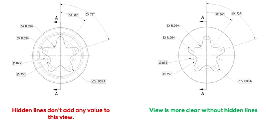
Logically, when one seeks to understand CNC drawings, it is important to know and appreciate that several resources highlight a few basic things. To begin with, it is very important to comprehend the scale since it determines how the dimensions will be reduced to actual sizes. For example, if any part is drawn to a power of two, such as a 1:2 scale, then any practical measurement should be half that of what is indicated. In addition, learning different types of lines used in instruments and understanding that solid lines are used for visible edges and dotted lines for hidden edges makes one refrain from misinterpreting the drawing.
Orientation I have encountered:
- Tolerances: Bryshov D. A. Jul 17, 2003: These are the allowable changes in dimensions from the standard, and they are critical since without them, parts wouldn’t fit well together. For instance, based on the given example, +/—0.01 mm is a really high tolerance.
- Surface Finish: Many parts will have a specified degree of surface smoothness. Characteristic parameters like ra average roughness also typically influence the design of a part.
- Material Specifications: A part may be made of mild structural steel, rigid aluminum, or many other materials, so understanding the machining processes and the tools needed is different. Every material has its machining parameters.
By effectively executing the above exercise, I have been able to master the essentials of my working tasks in navigating the CNC drawings, meeting the industry standards, and attaining satisfactory quality work.
Finding the Title Block and Understanding Callouts
As it is located in the title block of a CNC drawing, the box contains pertinent information about the part that is to be manufactured. Some examples include the part name, drawing number, scale, and designer’s name. This is important since it helps me figure out the details of a project within a short period.
Callouts are markers on the drawing, providing more instructions or directions about features or features’ instructions. Examples of such include parameters that are of a technical nature and may be related to:
- Dimensions: Provide exact dimensions for any or all combinations of length, width, height, etc., that will clearly indicate how large or small the part is.
- Tolerances: Shown on the drawing and define how many imperfections are acceptable for any of the manufactured parts as aforementioned.
- Surface Finish: Ra values are commonly used in callouts describing the degree of smoothening to be achieved.
- Material Type: The title block or complain bar alludes to which materials are to be used, referring to the fabrication methods.
Thanks to taking the time to look at the title block and especially the call-outs included in the drawings, I am able to appreciate all relevant requirements and specifications necessary for the piece’s successful fabrication while meeting the set quality standards.
Interpreting Complex Drawings: Guidelines
When faced with more detailed CNC drawings, I tend to proceed one step at a time. Here are some ways which I have found useful:
- Start with the Title Block: I have this habit of always going through the title block, as it contains most of the pertinent details regarding the part, like its name, drawing number, scale, etc. This is the most basic aspect that has to be observed in any drawing, and it is the context around which most documents revolve.
- Focus on Significant Dimensions: However, even more patience is required here, which is reserved for measurements given on the drawing. It is important to know how much of a certain dimension is to such an extent that it makes the fabricated parts interlock properly.
- Assess Tolerances: Tolerances define the degree to which ‘dimensions may vary from the prescribed dimension.’ Such measurements are difficult for manufacturers, especially when they are constructing or installing the parts. Machining tolerances, however, are relative and can be different depending on the type of material being machined and the use of the object machined.
- Surface Finish Specifications: I pay attention to and note any surface finish indications, such as Ra values. I am familiar with the requisite finish and, therefore, can determine the appropriate techniques and tools specific to the activity, which will affect both the use and look of the item.
- Consult with Resources: When I encounter graphemes or annotations that are beyond my experience, I search the web for good resources for explanations. This might entail some research into industry publications or on websites of professional engineers.
- Draw on Experience: Every drawing contains specific features. Recalling some aspects of why certain parameters were applied in previous works helps me better understand the new drawings that are being presented.
- Collaborate with Peers: If I am ever in doubt, talking to others about the drawings in question is often helpful, and one comes up with ideas they had not considered before or clarifications of issues. Various perspectives can illuminate complicated aspects.
Through such behaviors, I make it easier for myself to handle complex CNC drawings as required while maintaining the required standard and producing good-quality work.
What Things Should Be Considered in Limits and Fits for CNC Machining Drawings?

I apply several approaches to avoid confusion and inaccuracies in developing CNC machining drawings for various parts. To begin with, General Engineering Drawing standards dictate that all dimensions should be written clearly, legibly, and accurately, as this promotes healthy interaction. Also, While working in CAD, one should adopt a uniform layer management system because it aids in categorizing various types of information like dimensions, notes, and shapes. Removing doubts about what tools and materials the machinists should use and including pictures of those are also important points – usually for machined parts. In designing the parts, I try to restrain myself from going for complicated designs whenever possible. Instead, I let the part geometry be simple, which reduces the amount of engineering thought required to interpret them. Thanks to the definitions and notations widely used within the industry, the drawing is readable for all engineers and machinists who perform the manufacturing. Of course, drawing adjustment is the last step that every engineer should perform within his work, considering suggestions from any team or a client that would improve the drawing.
Top Tips for Effective Technical Drawing Preparation
Here is how I advise what to do:
- Understand the Standards: Understand the various standards prevalent in a particular bearing industry, such as ISO, ANSI, or German standards. This enables my drawings to adhere to standards that make them comprehensible to other professionals in the field.
- Utilise Appropriate Software: Choose CAD software that has the tools required for proper drawing and is friendly to use, such as AutoCAD or Solidworks.
- Maintain Consistency in Fonts and Symbols: Ensure that all text and symbols are similar in case and font size so that reading them is easy and the drawing’s comprehension is enhanced.
- Layer management: I use layers to distinguish between different elements of the drawing, such as dimensional items, annotation items, and geometrical items, making changes and clarifications simple.
- Incorporate Accurate Dimensions: Use dimension styles when annotating your engineering drawings that promote the use of best practices in supporting the various measurements in drawings to avoid any confusion on the sizes and/or tolerances of the parts.
- Provide Clear Annotations: I include reminders and detailed notes related to how the part is manufactured, the materials used, and the degree of tolerances, thus reducing the chances of vagueness and misinterpretations.
- Review for Clarity: Before declaring the completion of my drawings, I go through the final drawings very carefully and ensure they are clear and complete so that anyone looking at the drawing can easily understand the written directions.
- Feedback and Collaboration: I value the opinions of my co-workers and make it a point to obtain their perspectives and comments on issues because some of us are slow to notice things that need to be improved.
- Document Control: I use document control measures to track changes made and mitigate cases of drawing errors, such as confusion about which type of drawing is the latest.
- Continuous Learning: I keep myself up to date with changes in drafting skills and tools, which assists me in improving my competence and relevance in the work.
I hope these tips will help me deliver excellent technical drawings with appropriate team collaboration and compliance with standards.
Common Mistakes to Avoid in CNC Drawings
When performing CNC drawing, I should pay attention, as mistakes must be avoided, which would otherwise result in resource waste.
- Providing Incorrect Dimensions: Another mistake often committed is providing incorrect dimensions on the drawings. It is important to control all the dimensions and apply a proper tolerance system if any (for instance, ±0.01mm) because such errors will affect machining operations.
- Material Requirements Imprecise: Not including materials may also create problems during production and misunderstandings. I provide the type of materials (e.g., Aluminium 6061 or Steel A36) and specific finishes where appropriate.
- Different Styles of Annnotations: Applying annotation styles of different designs may cause disorganization. I avoid this problem by applying uniform methods of making annotations to avoid confusion regarding my drawings and the use of standards such as ISO and ANSI in the drawings.
- Missing Tool Paths Information: Tool path information, such as feed rates (200 mm/min) and spindle speed (1500 RPM), is important, and I make sure it is given in the CNC part.
- Complete Freedom in the Use of Symbols: I have to use the standard symbols for the features, surface finish, welds, etc., as per the norm (ASME or ISO, etc.).
- Neglecting to Take the Machining Constraints into Account: Forgetting the knowledge regarding the abilities and limits of the CNC machine, such as its maximum depth or toolholder constraint, is one of my shortcomings. Such consciousness is necessary for the creation of manageable sketches.
- Sketches Have Inadequate Technical Drawings: Insufficient detail may be misinterpreted. Even though my standing is limited, I provide additional views, sections, and detail drawings to ensure that important qualitative markers are all included.
- Failing to Document Revision History: I sometimes forget to show revisions as many times as I should. It is essential to ensure that revision history is available and that each revision is accurately demonstrated, including its effect on the end product.
- Unnecessary Complication: Some concepts I try to design, but scalp even a single part, keeping it as basic as possible and on a level that wouldn’t increase the chances of making mistakes due to extra processes or developments.
- Not Performing the Due Diligence Before Submission: Lastly, I plan to carry out their own miscellaneous scrutiny and revisions to all drawings at the point of submission. The completeness and clarity of the document are checked, as well as the conformity of the specifications to be implemented to the manufacturing processes, in order to prevent grave wastage in terms of time when the product is being processed.
Though these mistakes are fundamental and can occur in the normal course of work, preventing them will help me achieve precision and clarity in my CNC drawings, thus preparing them for manufacturing purposes.
Resources for Self-learning CNC Drawing Techniques
As I desire to improve myself in CNC drawing techniques, I have procured some useful resources popular on Google. Below are some of the most remarkable:
- YouTube: Other people, like channels CNC Kitchen and Paul McWhorter, share videos that demonstrate the essential elements of CNC techniques, such as G-code generation and tool path planning.
- Online Courses: Websites such as Udemy and Coursera also offer systematic courses on CNC drawing software applications in CAD. I especially like those modules that treat tolerancing and dimensioning; this is very important in designing and drafting documents.
- Forums and Communities: Sites like reddit.com/r/CNC and CNCzone help share information and solve problems. Topics include simple errors and best practices for machining revisiting and revisions.
- Textbooks: Other types of reference books, like Machinery’s Handbook and CNC Programming Handbook, contain all of the necessary information on tools, speeds, feeds, and calculations that I can use in my drawings.
- Software Documentation: CAD software solutions like AutoCAD or SolidWorks come with manuals, which include instructions on how to make technical drawings. The manuals also include instructions on symbol standardization and dimensioning practices.
- Industry Standards Organizations: Websites like ASME and ISO provide abundant information on acceptable symbol standards and drawing practices. By adhering to their instructions, my drawings will meet the particular industry’s standards.
- Webinars and workshops: Several organizations hold live sessions that introduce new developments in CNC technologies and best practices. These are healthy ways of developing me in terms of industry trends and technical parameters.
- Blogs and Articles: Sites like CNC Cookbook and Tormach’s blog tend to post articles on machining practices and case studies, which, in my case, have served as secondary resources to reinforce my ideation regarding the importance of detail and CNC drawing simplicity.
- Local Community Colleges: Taking classes, which are usually courses concentrating on CNC engineering, can also be helpful. These courses usually include theoretical parts like tooling employability and ‘constructive’ machine elaborates to create practical drawings that will serve their intended purposes.
- Professional associations: Patients in groups, such as the Society of Manufacturing Engineers, have assisted me in learning about industry advancements. This gives me a wealth of information on advanced technologies, which I can incorporate into my drawing practices and also ensure that I take into account the existing and emerging requirements.
Thus, using these tools helps me minimize mistakes that can occur when practicing CNC drawing techniques, and improves the quality of designs.
Conclusion – CNC Machining Drawing

In conclusion, to understand everything associated with cnc machining drawing, one must incorporate many components to achieve the necessary effectiveness. It is possible to improve one’s skills and knowledge of CNC practices, especially through industry standards and education, as well as through professional organizations. Trim zoning in the design process is done with ample attention to their understanding of simplicity and clarity in designs that govern the machining processes and enhance efficiency and effectiveness on the achievements at hand. Further to this, as one progresses in this discipline, old skills, in this case, will be rendered useless, and therefore, one will have to learn new skills to cope with the situation in CNC machining. Drawing on the understanding and experience, particularly from various means, will make it possible for me to deliver quality CNC drawings that would meet the needs of the industry.
Reference Sources
- CNC Programming Handbook by Peter Smid
This comprehensive guide covers a wide range of topics related to CNC machining, including programming techniques, tooling standards, and best practices for creating effective drawings. It serves as an authoritative resource for both beginners and experienced machinists.
- Fundamentals of CNC Machining by David E. Smith
This book provides foundational knowledge of CNC machining processes, including practical insights into the design and execution of CNC drawings. Including real-world examples helps validate the information discussed in the context of industry standards and practices.
- Society of Manufacturing Engineers (SME)
The SME website offers a wealth of resources, including technical papers, industry reports, and standards related to CNC machining. This platform is an invaluable tool for professionals looking to stay updated on the latest technologies and practices.
Frequently Asked Questions (FAQs) – CNC Machining Drawing

Q1: What is CNC machining drawing?
A CNC machining drawing is a technical illustration that outlines the specifications, dimensions, and details necessary for manufacturing a part using Computer Numerical Control (CNC) machines. These drawings serve as a blueprint, guiding machinists throughout the machining process.
Q2: What software is commonly used for creating CNC drawings?
Popular software for CNC drawing includes AutoCAD, SolidWorks, and Fusion 360. These programs provide tools for creating detailed designs, managing components, and generating toolpaths for CNC machines.
Q3: How do I ensure the accuracy of my CNC drawings?
To ensure accuracy, it is crucial to follow established design standards, double-check measurements, and use precise tools during the drafting process. Additionally, conducting simulations within CAD software can help identify potential issues before physical machining begins.
Q4: Are there specific standards for CNC drawings?
Several standards, such as ISO and ANSI, govern CNC drawings. These guidelines dictate the format, dimensions, and symbols used in technical drawings, promoting consistency and communication across the industry.
Q5: What is the importance of tolerances in CNC machining drawings?
Tolerances specify the allowable variance in dimensions, which is critical for ensuring parts fit together correctly and function as intended. Properly defined tolerances minimize errors and enhance the overall quality and reliability of the machined products.


