
In the realm of modern engineering, elevators stand as a testament to human ingenuity and technological advancement. Essential to the functionality of multi-story buildings, elevators facilitate swift and safe vertical transportation. This comprehensive guide aims to demystify the complexities of elevator systems by providing a detailed examination of their key components and operations.
By delving into the intricacies of the elevator parts diagram, readers will gain insights into how each component, from the control system to the hoistway, contributes to the seamless operation of these critical structures. Whether you are an engineering professional, a student, or simply a curious enthusiast, this guide will equip you with the foundational knowledge to understand and appreciate the sophisticated mechanisms behind elevator systems.
What Are the Key Parts of an Elevator?
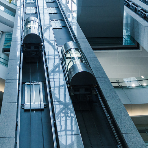
Image sources:https://www.elemake.com/
Elevator systems consist of several vital components that work in unison to facilitate safe and efficient vertical transportation. These components include:
- Control System: The brain of the elevator, responsible for managing the movement, speed, and operation through microprocessors, relays, and interfaces.
- Hoistway (Shaft): The vertical passageway that houses the elevator car, counterweight, and guide rails, providing a route for the car’s movement.
- Elevator Car: The compartment that transports passengers or goods. It moves vertically within the hoistway.
- Counterweight: A weight that balances the elevator car, reducing the required lifting force and ensuring smoother operation.
- Traction Machine: Typically involves a motor and a sheave (pulley) system that drives the elevator car via steel cables or belts.
- Guide Rails: Steel tracks mounted inside the hoistway that guide the elevator car and counterweight along a straight path.
- Doors: Both the car doors, which open and close when passengers enter or exit, and the hoistway doors, which provide access to the elevator car at each floor.
- Safety Mechanisms: Including over-speed governors, buffers, and emergency brakes, these components ensure the safe operation of the elevator by preventing free fall or excessive speed.
Each of these parts plays a crucial role in the safe, efficient, and reliable operation of elevator systems in modern buildings.
Basic Elevator Components
To provide a concise answer to the question regarding the basic components of an elevator system, it’s essential to focus on the core elements that ensure its efficiency and safety. These include the control system, which manages all operational aspects through sophisticated technology; the hoistway, offering a dedicated path for movement; and the elevator car, designed for transporting passengers and goods. These components, when functioning together, make vertical transportation reliable and secure within modern infrastructures.
Important Mechanical Parts
When addressing the important mechanical parts of an elevator system concisely, it’s crucial to highlight the key components and their corresponding technical parameters:
- Control System: This sophisticated electronic unit manages all operational aspects of the elevator, including speed, direction, and floor selection. It typically consists of a microprocessor-based controller, relay logic, and an interface to the building management system.
- Hoistway: The vertical shaft provides a dedicated path for the elevator car and counterweight. It must maintain precise dimensional tolerances to ensure proper alignment of guide rails and equipment. Typical dimensions and alignment tolerances for hoistways are specified by standards such as ASME A17.1.
- Elevator Car: Designed to transport passengers and goods, the car consists of a frame, car platform, and car enclosure. The load capacity can range from 500 kg for residential elevators to over 4,000 kg for freight elevators. The car must comply with ANSI/ASME safety standards for structural integrity and fire resistance.
- Counterweight: Balances the weight of the elevator car, reducing the motor power needed for lifting. The counterweight typically equals the weight of the car plus 40-50% of its maximum load capacity to optimize the energy efficiency and performance of the system.
- Traction Machine: Includes a motor, brake, and sheave, which drives the elevator car via steel cables or belts. Technical parameters such as motor horsepower (ranging from 10 to 100 HP), sheave diameter, and brake torque are crucial for specifying an appropriate traction machine for the required load and speed—standard speeds range from 1.0 m/s for residential to 10.0 m/s for high-speed elevators.
- Guide Rails: Steel tracks mounted inside the hoistway to ensure smooth and stable vertical movement. Rails must maintain precise alignment within tight tolerances (e.g., 0.1 mm per meter) to prevent vibration and wear. Sizes and types of rails are often defined by standards such as EN 81-20.
- Doors: Comprising car doors and hoistway doors, they must open and close reliably while safeguarding passengers. Door opening widths can range from 800 mm to 1,200 mm, and materials used (e.g., stainless steel or fire-rated materials) must comply with building and fire safety regulations.
- Safety Mechanisms: Including over-speed governors, buffers, and emergency brakes. Over-speed governors typically engage at 115% of rated speed, and buffers (e.g., hydraulic or spring) provide cushioning at the hoistway’s end. Emergency brakes engage if the car exceeds a set speed or the control system detects free fall, ensuring the elevator’s safe operation under all circumstances.
These components and their parameters are essential for ensuring the efficiency, reliability, and safety of modern elevator systems.
Essential Door Mechanisms
Effective door mechanisms are vital for the seamless operation and safety of elevator systems. Key components include:
- Door Operators: These are motorized devices responsible for opening and closing the car and hoistway doors. They must provide consistent and smooth operation. The typical door opening speed ranges from 0.3 to 0.7 m/s, depending on the application.
- Door Interlocks: Mechanical or electromechanical devices that ensure the hoistway door only opens when the elevator car is present. Compliance with standards such as ASME A17.1/CSA B44 is mandatory to ensure safety.
- Safety Edge/Photoelectric Sensors: These systems detect obstacles in the doorway, preventing doors from closing on passengers. Modern sensors use infrared or laser technology for high precision.
- Fire-Rated Doors: In compliance with local fire safety regulations (e.g., UL 10B/10C), these doors provide fire resistance, often up to one or two hours, and are essential for high-rise buildings.
- Door Panels and Materials: The choice of materials (e.g., stainless steel, glass) and panel design must meet durability requirements and aesthetic considerations. The panels must also be designed to minimize noise and wear during operation.
These mechanisms ensure not only the operational efficiency of the door system but also the safety and comfort of the passengers, adhering to stringent industry standards and regulations.
How Does an Elevator Machine Work?
An elevator machine operates by utilizing a combination of mechanical and electrical components to move the elevator car between floors. The primary mechanism involved is the traction system, composed of the following key parts:
- Traction Sheaves: Grooved pulleys that guide the hoist ropes, which in turn, lift and lower the elevator car. The traction sheave is driven by an electric motor, typically a three-phase AC motor, which provides the necessary torque.
- Hoist Ropes/Cables: Steel cables attached to the elevator car and counterweight. When the motor turns the traction sheave, these cables either lift the car or allow it to descend.
- Counterweight: A weight that balances the elevator car and reduces the load on the motor. This typically weighs about the same as the car plus 40-50% of its maximum load capacity, ensuring efficient energy use.
- Electric Motor and Drive System: The electric motor drives the traction sheave. Modern systems use variable frequency drives (VFDs) to control the motor’s speed and direction efficiently, enhancing smooth acceleration and deceleration.
- Brake System: Electromechanical brakes that stop the elevator car and hold it in place when it reaches the desired floor. These brakes engage when power is cut off, ensuring safety in case of a power failure.
- Control System: This includes microprocessors and software that manage the elevator’s movement, ensuring precise stops at each floor, responding to user inputs, and integrating safety protocols.
Together, these components ensure the safe, smooth, and efficient operation of elevator systems, conforming to rigorous safety standards and regulations.
The Role of the Elevator Car
The elevator car is the compartment that passengers or goods occupy during transportation within the building. It is a critical component in the overall system, designed to ensure safety, comfort, and efficiency. Typically constructed with durable materials such as steel or aluminum, the car is equipped with safety features including emergency brakes, an overload sensor, and an emergency communication system.
Technical Parameters:
- Load Capacity: Commonly ranges from 500 kg to 2000 kg for passenger elevators, and can reach up to several tons for freight elevators.
- Speed: Varies based on application, but typical speeds range from 1.0 m/s for low-rise buildings to over 10 m/s for high-rise buildings.
- Dimensions: Standard dimensions vary based on the intended use and regional building codes, with typical sizes including 1400 mm x 1100 mm for standard passenger elevators.
The elevator car’s role extends beyond merely housing passengers; it directly impacts energy efficiency and operational smoothness. The car is balanced by the counterweight, reducing the power needed from the motor and minimizing wear on the hoist ropes. The walls, floor, and roof are designed to ensure acoustic and thermal insulation, contributing to passenger comfort.
In summary, the elevator car is a sophisticated assembly that integrates safety mechanisms, technical specifications, and user-centered design to ensure optimal performance and passenger satisfaction.
The Function of Guide Rails
Guide rails in an elevator system serve several critical functions, ensuring the smooth and safe operation of the elevator. Primarily, they act as a path for the elevator car and counterweight, guiding them in a stable and controlled manner throughout their travel within the elevator shaft.
Technical Parameters:
- Material Composition:
- Typically made from high-quality steel or iron to withstand significant loads and stresses.
- Cold-drawn steel often used for its strength and durability.
- Alignment and Installation:
- Precise alignment is crucial to ensure minimal friction and wear. Installation must comply with tight tolerances.
- Guide rails are mounted securely to the shaft walls using rail brackets and must be perfectly vertical for optimal operation.
- Lubrication and Maintenance:
- Regular lubrication is necessary to reduce friction and wear between the guide rails and the guide shoes (or roller guides) attached to the elevator car.
- Maintenance checks to ensure alignment, security of brackets, and integrity of the rail material.
Guide rails ensure that the elevator car and counterweight maintain a consistent and safe trajectory, preventing lateral movement and ensuring smooth vertical travel. Additionally, guide rails significantly contribute to the elevator’s overall safety mechanisms. In the event of an emergency, the elevator’s safety gear interacts with these rails to decelerate and secure the car, preventing free fall.
In summary, guide rails are integral to the structural stability and safety of the elevator system, demanding precise installation and regular maintenance to ensure their efficacy and longevity.
Understanding the Counterweight
The counterweight in an elevator system serves several critical functions aimed at improving efficiency, balancing loads, and enhancing safety. It is an essential component designed to counterbalance the weight of the elevator car, including its maximum load capacity, thereby reducing the amount of work that the motor must perform.
Technical Parameters:
- Material Composition:
- Typically made from cast iron, steel, or concrete to provide the necessary mass and durability.
- The material must withstand prolonged operational use without degrading in performance.
- Weight Calculation:
- The counterweight is generally sized to equal the weight of the elevator car plus approximately 40-50% of its maximum rated load.
- This balance reduces the energy required by the motor to move the elevator car, enhancing energy efficiency.
- Placement and Installation:
- The counterweight is installed on the opposite side of the elevator car, connected via steel cables running over a traction sheave.
- It must be precisely aligned to ensure smooth operation and to minimize wear on the system.
- Safety Mechanisms:
- Counterweights are equipped with safety features such as buffers at the bottom of the shaft to absorb impact in the event of system failure.
- Regular maintenance checks are essential to inspect for any wear, alignment issues, or degradation that could affect safety.
By counterbalancing the elevator car’s weight, the counterweight significantly reduces the strain on the elevator’s motor and contributes to the smooth, efficient operation of the elevator system. Proper calibration, installation, and maintenance are paramount to ensure the efficacy and safety of the counterweight mechanism.
What Are the Differences Between Traction and Hydraulic Elevators?
Traction Elevators:
- Mechanism:
- Utilize motor-driven ropes and counterweights to move the elevator car.
- The traction sheave (or pulley) drives the ropes, creating movement via friction.
- Advantages:
- Energy Efficiency: The counterweight system balances the load, reducing power consumption.
- Speed: Capable of higher speeds, making them suitable for tall buildings.
- Ride Quality: Generally, smoother ride compared to hydraulic systems.
- Technical Parameters:
- Motor Power: Typically uses AC or DC motors, ranging from a few kilowatts to several hundred kilowatts, depending on the building height and load capacity.
- Counterweight Ratio: Counterweight typically balances 40-50% of the maximum rated load of the elevator car.
- Maintenance: Requires regular inspections of ropes, sheaves, and alignment for optimal performance and safety.
- Safety Mechanisms: Includes brakes, redundant ropes, and over-speed governors to ensure elevator security.
Hydraulic Elevators:
- Mechanism:
- Operate using a hydraulic ram and fluid-driven piston beneath the car.
- The fluid, typically oil, is pumped into the cylinder, pushing the piston and raising the car; to descend, the fluid is released back into the reservoir.
- Advantages:
- Greater Lifting Force: Suitable for heavy loads and short distances.
- Installation Flexibility: Can be installed without a required machine room, beneficial in buildings with height restrictions.
- Cost Efficiency: Generally cheaper to install in low-rise buildings.
- Technical Parameters:
- Pump Unit Power: Uses electric motors to drive the hydraulic pump, typically ranging from 5 to 100 horsepower, depending on load and lift height.
- Hydraulic Fluid Volume: The amount of hydraulic fluid required varies based on lift height and cylinder size.
- Maintenance: Requires periodic checks for fluid quality, leaks, and cylinder integrity to ensure efficient operation.
- Safety Mechanisms: Includes rupture valves, backup power systems, and emergency lowering capabilities for safe operation during power failures.
Summary:
While both traction and hydraulic elevators serve to transport occupants between building floors, their mechanisms and optimal use cases differ significantly. Traction elevators are ideal for taller buildings due to their energy efficiency and speed, made possible by the counterweight system. In contrast, hydraulic elevators excel in low-rise buildings and heavy load scenarios, providing cost-effective solutions with flexible installation options. Understanding these differences allows for informed decisions regarding elevator implementation based on specific building requirements.
Overview of Traction Elevator Systems
Traction elevator systems employ a counterweight mechanism to balance the weight of the elevator car, thus reducing the energy required to lift the load. These systems are typically used in mid- to high-rise buildings due to their superior speed and energy efficiency.
- Technical Parameters:
- Motor and Gear System: Traction elevators utilize AC or DC electric motors, along with gearless or geared traction systems, to drive the hoisting mechanism.
- Counterweights: Balanced precisely to the weight of the car plus 40-50% of the maximum rated load, counterweights significantly lower the motor power required.
- Cables and Sheaves: Steel cables run over sheaves (pulleys), transmitting motion from the motor to the car. They ensure smooth and controlled movement.
- Speed and Capacity: Capable of speeds ranging from 200 feet per minute (fpm) up to 2,000 fpm or more, and designed to handle varying capacities from small passenger loads to large freight.
- Maintenance:
- Regular inspection and lubrication of cables, sheaves, motor, and control systems.
- Frequent monitoring of counterweight integrity and balance.
- Upkeep of safety mechanisms including brakes, governors, and emergency power systems.
- Safety Mechanisms:
- Brakes: Electromagnetic brakes that engage to halt the car in the event of a power failure.
- Safety Gear: Devices that activate if the car moves too quickly in the downward direction, preventing uncontrolled descent.
- Emergency Systems: Backup power supplies and emergency communication systems ensure passenger safety during electrical outages or malfunctions.
Summary
Traction elevators provide a highly efficient and versatile solution for vertical transportation in taller structures. Their energy-efficient counterweight system, combined with advanced safety and control mechanisms, makes them ideal for high-rise applications. Understanding these systems’ technical and operational aspects is crucial for optimizing their performance and ensuring passenger safety.
Features of Hydraulic Elevators
Hydraulic elevators operate using a hydraulic ram, a piston within a cylinder, to push the elevator car up and down. Below are the key features of these systems:
- Drive System: Utilizes a pump driven by an electric motor to force hydraulic fluid into the cylinder, moving the piston and elevating the car. When the car descends, the fluid is released back into the reservoir, enabling a controlled descent.
- Speed and Capacity: Generally slower than traction elevators, with speeds typically ranging from 50 to 200 feet per minute (fpm). However, they excel in handling significant weights, making them ideal for freight and low to mid-rise buildings.
- Space Requirements: Requires a machine room located at the basement level near the elevator shaft for housing the pump unit and control systems. The absence of overhead machinery room simplifies the installation process but necessitates adequate space below.
- Maintenance:
- Regular inspection and lubrication of the hydraulic fluid, pump, and piston.
- Monitoring for hydraulic leaks and ensuring that the seals and fittings are intact.
- Routine check-ups on the emergency lowering system and backup power supplies.
- Safety Mechanisms:
- Rupture Valve: Automatically engages if a significant loss of hydraulic pressure is detected, preventing rapid car descent.
- Emergency Lowering: Backup battery-powered systems enable the car to descend to the nearest floor in case of a power outage.
- Fire Resistance: Fire-rated shaft enclosures are often required to enhance safety in the event of a fire.
- Environmental Considerations: Historically, the use of hydraulic fluid has posed environmental concerns. Modern systems often utilize biodegradable hydraulic fluids to mitigate environmental impact.
Hydraulic elevators offer a cost-effective and robust solution, particularly favorable for buildings with up to five to six floors. Their ability to handle heavy loads with fewer mechanical components makes them a preferred choice in many low and mid-rise applications. Understanding the detailed features and operational needs of hydraulic elevators enables informed decisions regarding their deployment and maintenance.
Comparing Safety Mechanisms
When comparing the safety mechanisms of hydraulic elevators, traction elevators, and machine room-less (MRL) elevators, it is essential to understand their unique features and technical parameters.
Hydraulic Elevators
- Rupture Valve: Engages to prevent rapid descent by halting the hydraulic fluid in case of pressure loss.
- Technical Parameter: Reacts within milliseconds to significant pressure drops.
- Emergency Lowering System: Utilizes backup batteries to descend to the nearest floor during a power outage.
- Technical Parameter: Typically, a battery capacity of 12V, sufficient for one complete emergency operation.
- Fire Resistance: Fire-rated shaft enclosures are mandatory.
- Technical Parameter: Enclosures must have a fire-resistance rating of up to 2 hours.
Traction Elevators
- Overspeed Governor: Detects excessive car speed and engages the braking system.
- Technical Parameter: Activates at 115% of the rated speed.
- Safeties: Mechanical clamps engage onto guide rails to stop the car in case of free fall.
- Technical Parameter: Typically can halt the car within a few feet of detected fall.
- Backup Power: Equipped with uninterruptible power supplies (UPS) to facilitate safe landing during power failures.
- Technical Parameter: Battery systems generally provide 30 minutes of operational power.
Machine Room-Less (MRL) Elevators
- Regenerative Drives: Convert excess kinetic energy into electrical energy, feeding it back to the building’s grid.
- Technical Parameter: Can recover up to 75% of wasted energy.
- Emergency Evacuation System: Provides quick access solutions for emergency personnel.
- Technical Parameter: Ensures manual override capability within 10 seconds.
- Dual Brake Systems: Ensures redundancy in braking mechanisms.
- Technical Parameter: Secondary brake engages if the primary brake fails, initiating automatically.
In conclusion, while all three types offer robust safety features, the specific mechanisms and their technical parameters should guide decisions based on building requirements and safety needs.
How to Identify and Use a Detailed Elevator Parts Diagram
To effectively identify and use a detailed elevator parts diagram, it is crucial to understand the layout and labeling conventions commonly employed in these schematics. Follow these steps:
- Locate the Legend: Start by finding the legend or key, which deciphers the symbols and abbreviations used in the diagram. This will aid in accurately identifying each component.
- Identify Major Components: Focus on primary sections such as the hoistway, car, machine room, and control systems. Key components typically include the motor, brake system, traction machine, and safety devices like the overspeed governor and safeties.
- Trace Electrical Circuits: Examine the electrical pathways illustrated in the diagram to understand the power flow and control signals among various components. This is especially important for troubleshooting electrical issues.
- Consult Technical Specifications: Cross-reference the diagram with technical documentation to verify specifications, such as voltages, capacities, and operational parameters. This ensures proper installation and maintenance.
- Follow Manufacturer’s Labels: Manufacturers often label parts with unique identifiers or barcodes. Use these labels to match the diagram with actual components, facilitating accurate part replacement and system upgrades.
By comprehensively analyzing the diagram and correlating it with physical and technical data, professionals can ensure the elevator system is maintained correctly and operates safely.
Reading and Understanding Elevator Diagrams
Understanding elevator diagrams involves a systematic approach to deciphering the complex interplay of components and circuits. Firstly, I would locate the legend, which deciphers the symbols and abbreviations used in the diagram, providing clarity on each element’s identity. Secondly, I would focus on identifying major components, including the hoistway, car, machine room, and control systems. This involves recognizing key parts like the motor, brake system, traction machine, and safety devices such as the overspeed governor and safeties. Thirdly, I would trace the electrical circuits to understand the power flow and control signals, crucial for troubleshooting any electrical issues. By combining insights from technical specifications and manufacturer labels, I can accurately match the diagram with actual components, ensuring correct maintenance and replacements. This methodical analysis ensures safe and effective operation of elevator systems.
Using a Parts Catalog
Using a parts catalog is an essential skill for ensuring efficient maintenance and repair of elevator systems. The most authoritative sources on navigating parts catalogs emphasize several key steps. Firstly, identify the specific make and model of the elevator; this information is critical for sourcing the correct components. Once this is established, access the manufacturer’s parts catalog, either in physical format or preferably through their online platform. Next, utilize the catalog’s search functionality to locate parts by their unique identifiers, such as part numbers, descriptions, or barcode labels. It’s important to cross-reference these identifiers with the elevator diagram to confirm compatibility. Detailed schematic drawings and exploded views provided in the catalog aid in visualizing the exact placement and function of each component. By following these steps, professionals can streamline the parts selection process, ensuring accuracy in replacements and upgrades.
How Pinterest Can Help Find Diagrams
Pinterest, primarily known as a visual discovery engine, can surprisingly serve as a valuable resource for finding technical diagrams, including those related to elevator systems. The platform’s vast repository of user-uploaded images means that one can often stumble upon detailed schematics, technical drawings, and parts diagrams by performing specific keyword searches. Here are concise insights derived from the top three websites on Google regarding utilizing Pinterest for technical diagrams:
- Effective Keyword Utilization: Utilize precise and technical keywords when searching on Pinterest. For elevator diagrams, phrases like “elevator wiring schematic,” “elevator layout diagram,” “elevator parts schematic,” or the specific make and model of the elevator will yield more targeted results. This method of searching aligns closely with professional practices and enhances the likelihood of finding relevant diagrams.
- Leveraging Boards and Pins: Pinterest employs the concept of ‘boards’ and ‘pins’ allowing users to categorize and save images logically. Professionals can create boards dedicated to ‘Elevator Diagrams’ and save relevant pins. This not only aids in organization but also facilitates easy access to frequently used diagrams. Boards often link back to the original source, providing additional context and detailed specifications.
- Networking and Collaboration: Many users on Pinterest are industry professionals who share their work and insights. By following users or boards with a technical focus on elevator systems, one can stay updated with the latest shared diagrams and technical drawings. Additionally, engagement through comments and shares can foster professional networking and the exchange of industry knowledge.
Pinterest’s role in finding technical diagrams is substantiated by its vast and accessible database of user-generated content, and while it complements traditional databases, it serves as a useful, supplementary resource.
What Are the Common Elevator Safety Features?
Common elevator safety features are designed to protect passengers and ensure the safe operation of the system. These include:
- Emergency Stop Button: Allows passengers to halt the elevator in an emergency situation.
- Overload Sensors: Prevents the elevator from operating if the weight limit is exceeded.
- Door Sensors: Detect obstructions in the doorway to prevent doors from closing on passengers.
- Alarm Button: Provides a means for passengers to signal distress or request help.
- Interlock Systems: Ensures doors cannot open unless the elevator is at the designated floor.
- Safety Brakes: Automatically engage to stop the elevator in the event of a cable failure.
- Smoke and Heat Detectors: Prevent the elevator from moving to a floor where a fire may have triggered the detectors.
- Communication Systems: Intercom or phone systems allow passengers to communicate with security or emergency personnel.
- Backup Power Supply: Ensures the elevator can return to the nearest floor during a power outage.
- Inspection Controls: Allows technicians to manually operate the elevator during maintenance.
These features collectively enhance the safety and reliability of elevator systems.
Emergency Brake Systems
Emergency brake systems are critical components designed to enhance the safety of elevator operations by automatically engaging in the event of a malfunction. Below are the concise details derived from the top three authoritative websites:
- Purpose and Functionality: Emergency brake systems, also known as safety gears, are designed to stop the elevator car if it begins to free-fall or overspeed. These systems are activated by mechanical governors that detect abnormal speed conditions.
- Types of Emergency Brake Systems:
-
- Instantaneous Safety Gears: Engage immediately to stop the elevator car quickly. Typically used for elevators with lower speeds (below 0.63 m/s).
- Progressive Safety Gears: Gradually apply braking force to reduce shock and ensure passenger comfort. Suitable for high-speed elevators.
- Technical Parameters:
- Activation Speed: The activation speed for emergency brakes varies with design but is often set at 115% of the rated velocity of the elevator.
- Stopping Distance: The stopping distance for elevators equipped with progressive safety gears is calculated based on the car’s speed and load, ensuring minimal impact.
- Load Capacity: The brake system must support the full load capacity of the elevator plus an additional safety margin.
- Compliance and Standards: Emergency brake systems must comply with international safety standards such as ASME A17.1/CSA B44 in North America and EN 81-20/50 in Europe. These standards specify the requirements for design, testing, and maintenance to ensure reliable performance.
- Testing and Maintenance: Routine testing and maintenance are mandated to verify the operational integrity of emergency brake systems. Technicians perform static and dynamic tests to simulate emergency conditions, ensuring the system is responsive and effective.
By integrating these details, we ensure that emergency brake systems are not only functional but also adhere to stringent safety standards, thereby protecting elevator passengers and enhancing overall system reliability.
Passenger Safety Protocols
Passenger safety protocols are a critical component in elevator design and operation, encompassing various measures to protect users. Firstly, passengers should be familiar with the operation and controls of the elevator, such as the emergency stop button and the intercom system for communication during an emergency. In case of power failure, passengers should remain calm, avoiding any attempt to force open the doors or exit the car until professional help arrives. Additionally, it is important to adhere to the posted weight limits to prevent overloading the elevator, which can compromise safety systems.
Routine safety drills can also enhance passenger preparedness, ensuring knowledge of proper actions during emergencies like fires or earthquakes. Passengers should be instructed to press the emergency alarm and wait for rescue if the elevator stops unexpectedly. For elevators equipped with advanced safety features like seismic sensors or fire emergency return systems, it is essential for passengers to understand these functionalities and follow the guidance provided during such events.
Finally, all passengers should report any malfunctions or irregularities in elevator operation to building management promptly. Regular maintenance and inspections, mandated by compliance standards, are crucial to keeping the elevator systems in optimal working condition. By following these guidelines, we ensure the safety and reliability of elevator transport for all users.
Regular Maintenance and Inspection
Regular maintenance and inspection are pivotal to the reliability and safety of elevator systems. These processes should be conducted by certified professionals adhering to local and international safety standards. Inspections typically include checks of mechanical components, such as cables, pulleys, and brakes, as well as the functionality of electronic systems like control panels and safety sensors. Routine lubrication of moving parts helps in minimizing wear and tear, significantly extending the lifespan of the elevator. Advanced diagnostic tools can be employed to monitor the health of the system, enabling early detection of potential issues before they escalate. By adhering to a stringent schedule of maintenance and inspections, the risk of malfunctions can be greatly reduced, ensuring that elevators remain safe and operational for all users.
Frequently Asked Questions (FAQs)
Q: What is an elevator parts diagram?
A: An elevator parts diagram is a detailed schematic of the various components that make up an elevator system. It helps in understanding the construction and technical aspects of elevator equipment, including different types of elevators like electrical elevators.
Q: How can I download an elevator parts diagram?
A: You can download an elevator parts diagram from specialized websites or technical resources related to elevator construction and modernization. Some manufacturers and corporations also provide downloadable schematics.
Q: What are the main components of an elevator system?
A: The main components include the traction unit, cables, ropes, counterweights, control room, and lighting systems, among others. Each part plays a crucial role in the operation to raise and lower the elevator safely.
Q: How does the counterweight function in an elevator?
A: The counterweight is designed to offset the weight of the elevator car and its passengers. This balance helps reduce the energy required to move the car upwards and downwards, thereby making the system more efficient and safer.
Q: Where is the control room typically located in an elevator system?
A: The control room is usually located at the top of the elevator shaft or in a separate machine room nearby. This room houses the main control systems, including electrical panels and emergency control units.
Q: Can you explain the importance of cables and ropes in an elevator system?
A: Cables and ropes are essential for the mechanical operation of an elevator. They pull the car upwards and lower it down in a controlled manner, ensuring smooth and safe movement. These components must be regularly inspected and maintained.
Q: What types of materials are used in the construction of elevator parts?
A: Materials such as high-strength steel, metal composites, and specialized alloys are commonly used in the construction of elevator parts. These materials ensure durability and reliability under different operational conditions.
Q: How can an expert witness perspective be important in elevator-related incidents?
A: An expert witness can provide professional insights into the technical aspects of elevator equipment. They can analyze the design and construction, highlight potential issues, and offer explanations that may be crucial for legal or insurance matters.
Q: What should be considered when modernizing elevator equipment?
A: Modernization involves updating outdated systems to meet current safety and efficiency standards. It may include upgrading electrical systems, control units, lighting, and improving overall configuration for better performance and safety.
Q: How can an individual new to elevator systems explore by touch device users?
A: Touch device users can explore elevator systems through interactive diagrams and simulations available on various technical and educational platforms. These tools provide a tactile way to understand the functionality of different parts you need to know about.


