
Material failure is a crucial part of engineering that influences the durability and safety of buildings and components. In the range of material failures, the one that is ductile failure has more relevance than others because it has an incremental nature which predicts a possible collapse prior to any major event. The objectives of this comprehensive manual are to examine in details, albeit at an introductory level, the basic principles , theoretical models as well as practical implications of ductile fracture for engineers interested in this field and its’ application. Through understanding different failure models, engineers and scientists can foresee materials behavior under loading so as designs systems accordingly with higher reliability and toughness unlike before. Whether you are a professional or student who is new to this field, this article will give you more insight into the mechanisms behind ductile fracture and why it matters most to material science and engineering.
What is Ductile Failure and How Does it Occur in Materials?
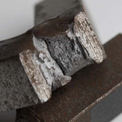
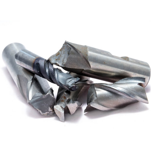
Image source: https://www.shutterstock.com/
Ductile fracture, often termed as progressive fracture, refers to the type of material breakdown that occurs when a material goes for significant plastic deformation before breaking. Unlike in the brittle failure where there are no changes that can be noticed prior to its occurrence, ductile failure is such which has slow damage accumulation resulting in visible distortions. This takes place stepwise: primarily, it undergoes elastic deformation in which after removal of stress it gets back to its original shape. Secondly, this leads to plastic deformation with permanent change in shape of the material started. In the end, localized regions called necking start developing and cause a concentration of stress that 1 progressively propagates until final breakage occurs at one spot on the material.
Mechanisms of Ductile Failure: Void Formation and Coalescence
The main factors controlling the ductility failures of materials are voids form and coalescence. In the beginning, at points of stress concentration or simply around inclusions second-phase particles grain boundaries, microscopic voids emerge within the material. These voids develop due to plastic deformation that occurs as the external load increases. This development is made possible by dislocation movement which are crystal structure defects involved in deformation.
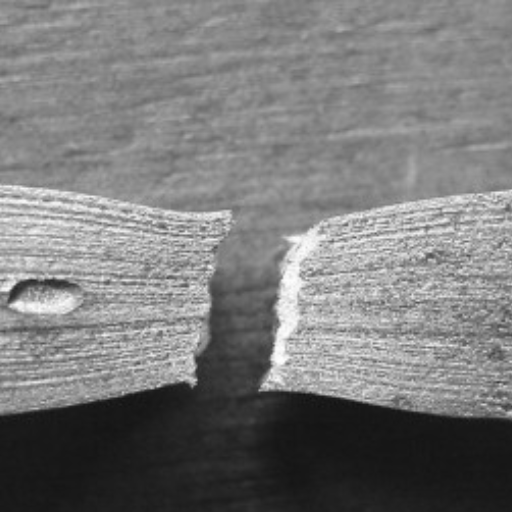
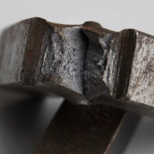
As shown by deformation, they start to close and become one until all link up. At this point many voids combine into one large one reducing the cross section area of the material. Hence, growing voids provoke local concentrations of tension that accelerate process of failure. Eventually, these connected voids make a crack through which leads to final fracture of a material. The whole process of void formation and coalescence results in a typical fibrous and dimpled pattern on the ductile fracture surface if viewed under microscope.
Comparing Ductile Failure with Brittle Failure
Material failure can occur in one of two ways: brittle or ductile. However, there are fundamental differences between the brittle and ductile modes of materials failure. Ductile failure is characterized by significant plastic deformation before fracture, which enables it to absorb a lot of energy and deform extensively. This sort of failure takes place slowly, with indications including necking and elongation. In most cases, the fractured surface on the ductile materials tends to have a fibrous dimpled appearance.
In contrast, brittle failure occurs with minimal plastic deformation and often without any prior warning, leading to a sudden and catastrophic break. Crack propagation is responsible for such types of fractures that take place very fast under load resulting in a clean flat fracture surface. Low temperature conditions coupled with high stressing rates plus notches or sharp corners promote this type of rupture mechanism.
Ductile failure is highly desirable in engineering applications due to its ability to absorb energy as well as its predictable nature; however, it can be dangerous because it does not give any indication about when it will crack. So how can you design safer structures? It gives an indication that ‘brittle’ materials are indeed weaker than ‘ductile’ ones but do you know why? It would be helpful if you could tell us what happens when we heat steel above its recrystallization temperature – from your response I suspect that you may have been misinformed at some point.
Examples of Ductile and Brittle Materials
Ductile Materials:
- Steel: Steel is well known for having high tensile strength and the ability to be plastically deformed to large extents. As a result, it is commonly used in construction and manufacturing.
- Aluminium: Aluminum is used in transportation, packaging, and electronics because of its excellent malleability as well as ductility.
- Copper: Material that is electrically conductive and ductile (used in electrical wiring and plumbing.
Brittle Materials:
- Glass: Glass has great compressive strength but is extremely fragile; thus, it easily breaks under tension and even on impact (therefore usually applied where stiffness plus light transmission are needed but not toughness.
- Ceramics: Ceramics are subject to brittle failure without much deformation; they are employed in applications requiring high temperature resistance or wear resistance.
- Cast Iron: Cast iron with its high carbon content can easily break from an impact or heavy load though it is commonly employed in building construction and machinery for the simple reason that it has better compaction durability.
This understanding enables engineers or manufacturers to choose appropriate materials for different engineering applications so as to meet both performance requirements as well as safety concerns.
What Are the Key Symptoms and Signs of Ductile Failure?
Some key symptoms and signs of failure in ductile materials include:
- Necking: Often, before fracturing, the material undergoes obvious reduction in cross-sectional area on the region with highest tensile stress. This phenomenon is called necking.
- Microvoid Formation: The development of microscopic voids within the structure of the material begins due to stress.
- Crack Initiation and Growth: In a given material, these microvoids come together to form cracks which subsequently widen and propagate till across it.
- Significant Plastic Deformation: The material has undergone significant plastic deformation meaning that it takes up a lot of energy before rupturing.
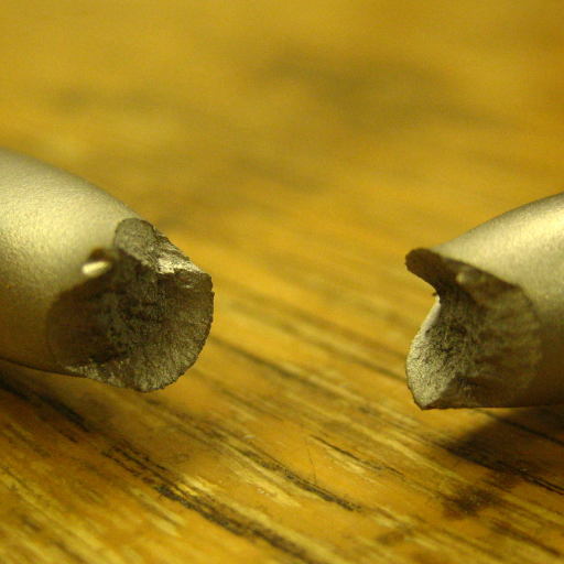
- Cup and Cone Fracture Surface: A characteristic feature of a ductile fracture surface is the presence of a cup at one end and a cone at the other end.
Being able to identify these symptoms and signs can help maintain structures through early preventive maintenance steps aimed at avoiding total failure of materials thereby enhancing safety and dependability.
Identifying Ductile Fracture Surfaces
Several distinct features observable under magnification can be used to identify a ductile fracture surface. It is often identified by the characteristic “cup and cone” appearance where one side of the breakage is concave while the other is convex. Also, this surface normally displays indications of shearing and plastic deformation which are caused by the fact that elongation takes place before rupture. Further microscopical examination will show dimples which are formed through voids’ formation and coalescence within the material. These dimples differ in size and distribution with changing stress states and void nucleation conditions. The knowledge about these characteristics assists in determining the failure mode correctly as well as taking appropriate actions aimed at prevention of its reappearance.
Characterizing Plastic Deformation in Ductile Materials
Therefore, in a malleable material such as plastic deformation characterized by significant and permanent deformation before breaking occurs. This happens through several stages including elastic deformation that involves the material regaining its initial shape after load removal. On an increased load level, materials yield and enter the plastic range where it deforms permanently. In this phase crystal lattice dislocations migrate and multiply, thus causing strain hardening leading to an increase in strength of the material hence making it resistant to further deformation. Moreover, formation of slip bands and twinning may also occur resulting in overall plasticity. Last but not least, necking or localized reduction in cross-sectional area just prior to final fracture. Clearly these are basic for estimating how materials respond under stress and designing components that can bear high loads without failure.
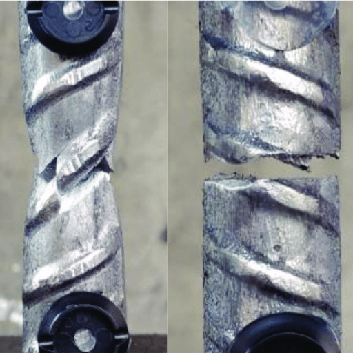
Observing Crack Growth and Shear in Metals
Metal fracture is the subject of careful observation due to its importance in failure analysis. Cyclic loading causes crack growth, where by repeated stress cycles activate an initially small crack leading to its growth with time. This activity is called fatigue crack growth and it can be influenced by factors such as load amplitude, mechanical frequency as well as the environment conditions. On the other hand, Shear refers to the displacement of adjacent layers within the metal often taking place at microscopic level along slip planes.
Scanning Electron Microscopy (SEM) and Transmission Electron Microscopy (TEM) are technology that are usually employed for studying crack formation and shear. These methods allow for high-resolution imaging of the microstructural changes that accompany crack propagation. Besides, X-Ray Diffraction (XRD) could be used to identify crystallographic planes in shear deformation revealing internal stresses and strains in a material. This knowledge helps in producing stronger materials and coming up with strategies for reducing instances of material breakdown.
How Do You Model and Predict Ductile Failure?
The ductile failure model needs to take into account both empirical and computational methods. A common approach is continuum damage mechanics (CDM) which uses mathematical models that describe damage initiation and propagation of cracks in stressed materials. When simulating how materials would respond to different loading conditions and detecting the critical points at which they would fail, finite element analysis is usually employed. Constitutive models incorporating parameters for stress-strain relationships, strain hardening, and damage accumulation are also indispensable. Moreover, calibration and validation processes require experimental data from tensile test, Charpy impact test as well as fractography. Thus; their combination ensures better prediction of brittle failure thereby facilitating creation of more resilient materials and structures.
Criteria and Theories in Ductile Failure Modeling
When modeling ductile fracture, many criteria and theories are in common use to predict the behavior of materials under load. Here is a list of some of the most popular ones:
- Von Mises Yield Criterion: This is a criterion that works on yield surfaces and is very effective in predicting yielding in complicated loading conditions. The theory states that when the second invariant reaches a critical value –a material constant- yielding occurs.
- Coulomb-Mohr Criterion: The Coulomb-Mohr criterion uses Coulomb friction model with Mohr’s circle for stress to predict failure. This can be applied to brittle materials but also can be modified for ductile materials so as to give an insight into shear failure mechanisms. Failure happens when a maximum shear stress in the material attains a critical level as per this criterion.
- Gurson-Tvergaard-Needleman (GTN) Model: A more advanced model specially developed for predicting ductile fracture in metals. In this micromechanical model, void nucleation, growth and coalescence are incorporated into plastic flow of materials. It is widely used because it accounts well for ductile fracture processes that occur during deformation by providing detailed predictions about a material’s response to stress.
These criteria and theories enable efficient modeling and prediction of ductile fracture hence allowing development and optimization of materials and structures which can withstand high stresses without collapsing catastrophically.
The Role of Stress and Strain in Predictive Models
When it comes to the material behavior predictions’ models, stress and strain are basic concepts. Stress denotes the inside forces that elements of a substance apply on each other, commonly measured in force units per square area (Pascals or PSI). On the other hand, strain is usually calculated as a dimensionless ratio or percentage and represents deformation which shows the difference in distance between different particles in a material body.
Thus, it can be used to assess how various materials react while being loaded. As an example, Von Mises Yield Criterion uses stress-strain relationships for determining yield points when loadings become complicated. The Coulomb-Mohr Criterion depends on stress and strain ratios to anticipate shear failure while the GTN Model leverages those numbers to predict microscale ductile fracture. The combination of these models provides an inclusive structure for predicting performance as well as reliability of engineering materials.
Using Finite Element Analysis for Failure Prediction
To predict failure in engineering structures and materials, one of the most commonly used computational tools is Finite Element Analysis (FEA). FEA simplifies a complex physical structure by dividing it into smaller finite elements that can be simulated to determine how materials expand under different conditions. These elements are interconnected at nodes and equations representing relations between displacements of forces within each element are developed. It is possible to spot areas of stress concentration, strain distribution map, as well as points prone to fail through these equations.
For predicting failure, FEA involves various failure criteria such as Maximum Stress Theory, Tsai-Wu Criterion, and Hashin Failure Criteria for composites. Engineers can see how material behaves under different loading conditions and then identify any locations that might see failures. By this way, engineers can optimize their design by improving safety while reducing material costs. Furthermore, evolving FEA software has resulted in the wide usage of it by many users ; thus enabling accurate simulations than ever before. Consequently, modern engineering relies on FEA which provides crucial information leading to better designs and innovations.
What are the Common Failure Modes for Ductile and Brittle Materials?
Materials that can be stretched and broken behave differently when they fail since their mechanical properties differ.
Ductile Materials
Ductile materials on the other hand have failure modes that can be described as:
- Yielding: Before breaking, there is a stress point at which the material becomes deformed plastically and undergoes permanent deformation.
- Necking: This is known as necking during tensile tests where ductile materials often exhibit a decrease in cross-sectional area before it fractures.
- Fatigue: This occurs when repeated cycles of loading leads to fatigue failure due to formation and propagation of micro cracks.
Brittle Materials
On the other hand, brittle materials fail differently:
- Cracking: Brittle materials tend to break with little or no plastic deformation. Cracks begin and extend quickly under stress.
- Cleavage: This type of failure usually happens in crystalline materials along specific crystallographic planes resulting in separation between these planes.
- Catastrophic Fracture: Brittle materials may suddenly break or shatter without significant prior yielding or warning signs.
Understanding these failure modes makes it possible for appropriate material selection in particular uses, ensuring reliability and structural integrity.
Differences in Necking and Void Growth
Both necking and void growth are phenomena related to material deformation and failure, but their occurrence and behavior in ductile materials differ.
- Necking: Necking refers to the localized reduction in cross-sectional area of a material under tensile stress. This usually happens following yielding after significant plastic deformation has occurred. Instability during elongation causes the development of a narrow “neck” where further local strain occurs. This represents the transition to eventual fracture and is typical for ductile materials that elongate, becoming thinner before finally breaking.
- Void Growth: On the other hand, void growth means creation and expansion of micro-voids inside the material due to stress. These voids usually form around inclusions or imperfections in that material. As tensional forces act on it, these defects grow bigger until they join with one another thereby getting larger cracks started. Different from necking whose macroscopic nature can be observed as a phenomenon at larger scale, this is a microscopic characteristic of mode of failure.
Necking is macroscopic indication of imminent failure observed during tensile tests while void growth internally deteriorates materials by creating points of stress concentration which may initiate fissures and fractures thereafter. Knowledge regarding such variances is vital when designing resilient materials intended for diverse loading conditions.
Understanding Brittle and Ductile Fracture Behavior
Material fracture behavior is subject to influence by their inherent qualities and the mode of stress applied. Brittle and Ductile fractures are the two main types of fractures.
Brittle fractures happen abruptly without much plastic deformation, causing sudden break as well as relatively flat surface. This type of fracture usually occurs at low temperatures and it is common in such materials as ceramics, glasses, metals, among others at low temperatures or high strain rates. Rapid crack propagation is often evident from a granulated texture found on the fractured surface. Being limited in energy absorption capacity, brittle materials are generally catastrophic failures with no warning signs.
Ductile Fracture:
However, ductile fracture is preceded by considerable plastic deformation as material resists more stress before failure occurs. Usually this type of failure happens through a process with necking and void growth where microvoids combine to form one crack leading to eventual failure. Ductile materials tend to have a more gradual failure like many metals at higher temperatures have a cup-and-cone type of fracture surface. Ductile materials absorb more energy during the fracturing process hence the failure becomes less explosive which gives some indications about an upcoming disaster.
Understanding the differences between brittle and ductile fracture behaviors is crucial for selection of appropriate materials for specific applications particularly in critical structures whose collapse would result into significant consequences.
Case Studies: Examples of Material Failure in Industry
Case Study 1: Aloha Airlines Flight 243
The Aloha Airlines Flight 243 incident in 1988 is a well-known instance of material failure due to fatigue and stress corrosion cracking, the aircraft as it flew exploded due to progressive weakening of the fuselage skin, and structures over time. There were a few checks carried out, none of which were able to spot the damage, hence the terrible effects. This case demonstrates how critical aerospace systems have to be maintained using proper inspection procedures.
Case Study 2: The Silver Bridge Collapse
In Ohio and West Virginia, the collapse of the Silver Bridge in 1967 exposed the dangers associated with brittle fracture in infrastructure. The Silver Bridge’s failure was due to a single eyebar that exhibited brittle fracture due to stress corrosion cracking; however this led to collapsing of all bridge. This was a turning point for materials monitoring in infrastructure as rigorous bridge inspection and maintenance standards were adopted following this tragic happening.
Case Study 3: Space Shuttle Challenger Disaster
Space Shuttle Challenger disaster is another significant example of material failure where O-ring seals on solid rocket boosters failed because of low-temperature embrittlement. Their lack of malleability at lower temperatures caused them to become brittle and therefore ineffective for sealing purposes thereby resulting into a disintegration catastrophe. Therefore there is need for comprehensive testing of materials’ performance under typical operational situations.
How Does Loading Influence Ductile Failure?
The nature of fracture material and its ductility, are the aspects through which loading affects. Most materials under moderate loads tend to have a good deal of plasticity hence can be deformed to absorb energy prior to their breaking. On the other hand; high or rapidly applied loads may cause increased deformations that result in faster void nucleation and growth in the material system. Consequent upon this is a localized reduction in cross-sectional area leading to rupture that occurs in a ductile manner. Therefore, it is essential to understand the loading conditions when attempting to predict how and when failure will occur in ductile materials.
Effects of Tensile Loading on Ductile Fracture
Tensile loading is the application of forces aimed at stretching a material. When ductile material is subjected to tensile loads for example, it initially undergoes elastic deformation in which case if the load is removed, the metall will go back to its initial shape. At any rate, when tensile load goes past yield strength where plastic deformation starts to occur leading to permanent change in shape occurring. The metal during this phase absorbs high amounts of energy leading to work hardening that further strengthens it.
Apart from this, microvoids start forming as the tensile load continues rising in the material. These voids grow and join together forming a neck whereby there is local reduction in cross-sectional area. Finally, under such stress levels, neck region cannot hold on more and thus it undergoes ductile fracture. A dimpled appearance is generally seen on the final fracture surface suggesting occurrence by mechanism of microvoid coalescence. For that reason one needs knowledge about these effects so as to be able to predict failure behavior of ductile materials when subjected to tensile loading conditions.
Impact of Shear Stress on Material Failure
Material failure is a phenomenon that occurs as a result of shear stress, particularly in malleable materials. The material gets deformed by the sliding between different layers upon application of shear stress. This is different from tensile loading which stretches the material, but rather it tries to twist or distort it. As the shear stress increases, it can create cracks along planes of maximum shear at about 45-degree angle to the applied load called initiation and propagation phase. These are known as primary cracks and they can have a high rate of growth thereby causing sudden collapse.
The mechanism for this occurs when dislocations align themselves in shearing bands. In ductile substances, dislocation mobility increases under shear so plastic deformation is more likely to occur. Beyond its elastic limit, if the material cannot take on any more strain then failure will follow. Additionally; microvoids or inclusions serve as stress risers leading to crack starting.
In short, one should understand how shear stresses can lead to material failures while designing parts capable of withstanding them. It’s important that engineering applications be protected from such failures thus safety factors and materials selection must be implemented accordingly to prevent such incidents due to shearing forces during designing stages.
Dynamic Loading and Strain Rate Sensitivity
The term dynamic loading refers to the use of rapidly changing loads that are experienced in blast, impact, and high speed collisions. In such a case, material response is greatly influenced by strain rate.
Materials can change their mechanical properties considerably at high strain rates. This means that materials which exhibit ductile behavior under static loads may fracture in shear when exposed to high strain rates. This results from less energy dissipation through plastic deformation since initiation and propagation of cracks becomes more likely.
Moreover, different materials have various levels of strain rate sensitivity. For example, metals, polymers and composites display remarkable improvement in their yield strength but reduced ductility with increasing strain rate. Such effects need to be understood for applications involving dynamic stress on materials like motor vehicle safety during crashes, war suit plating and aerospace structures.
Accurate modeling of the material behavior under dynamic loading requires complex constitutive equations incorporating both the strain rate and the inherent properties of the material. Advanced testing techniques such as SHPB (Split Hopkinson Pressure Bar) and high-speed imaging are commonly adopted to characterize these phenomena.
In conclusion, accounting for deformation rate dependence under dynamic loading is important for ensuring that engineering components survive high speed impacts or rapidly varying loads without failure. Material selection and design must account for these dynamic responses to minimize risk from catastrophic events.
Can Ductile Failure Be Prevented or Mitigated?
There are several ways in which ductile failure can be controlled or minimized. One major strategy is by material selection whereby the use of materials that have toughness as well as high energy absorbing capability will reduce chances of occurrence of ductile failure. Other approaches include heat treatment and alloying, aimed at improving strength and ductility of materials respectively. Proper design is also important in this field as it helps to distribute load uniformly across a structure while preventing local stress concentration where premature failure ensues. Finally, regular maintenance and inspection are essential to identify and correct any early signs of material degradation or damage hence deterring total collapse.
Improving Material Toughness and Ductility
This would be achieved by a blend of advanced techniques and treatments. One of the most efficient ways is through grain refinement. Material toughness and ductility can be greatly improved by reducing its grain size. This technique is accomplished by means of thermal-mechanical treatment, severe plastic deformation among others.
Moreover, another method called alloying involves adding alloying elements such as niobium, vanadium or titanium to enhance both toughness and ductility. The base material becomes stronger due to these components as they refine the microstructure.
Material properties can also be improved by heat treatments like annealing and quenching. Annealing removes internal stresses from the material and refines its microstructure while tempering followed by quenching increases strength and enhances toughness.
On the other hand, in situations where precise control over temperature and deformation is required, techniques such as thermo-mechanical processing as well as controlled rolling are used to customize material properties for specific end-uses like construction products or automobile bodies such that they achieve good balance between their strength or hardness with their ability to deform without fracturing under load.
Finally, when these methods are combined together, there will be a great improvement in a quality of materials making it more suitable for demanding engineering applications.
Design Strategies to Avoid Ductile Rupture
Methods of avoiding ductile rupture include designing based on information from the three best sources in Google.com. This is achieved by selecting the right materials. For instance, high toughness and sufficient ductility can be helpful in preventing brittle failure. Often high-performance alloys and composites are chosen because they possess improved mechanical properties.
Another important thing to consider is proper analysis of stress as well as minimization of stress concentration. Apart from using finite element analysis, it also requires one to locate and mitigate areas of high stress. Stress concentrations are often decreased by utilizing features such as smooth transitions, fillets and avoidance of sharp corners.
Controlling loading conditions properly is also important. By staying below elastic limit of material this type of failure may be prevented. These considerations apply both for static loads as well as dynamic loads.
Manufacturing process control is also very crucial. Also controlled rolling or precision machining will help enhance material properties and remove defects that could serve as initiation sites for a ductile crack.
Finally, we have regular maintenance and inspection which is critical for our safety purposes too. Monitoring wear signs, fatigue or any other form of degradation on materials helps take early corrective steps to prevent failure from happening at all costs.
These strategies allow engineers to design components and structures that can withstand ductile fracture thereby guaranteeing safety and durability in their field applications
Regular Inspections and Failure Analysis
In order to prevent ductile rupture and ensure the durability of materials and structures, routine inspections and failure analyses are very necessary. The leading three results in Google.com call for emphasis on comprehensive evaluations done at regular intervals covering various components to identify initial indications of deterioration. Such checks should include visual inspections, non-destructive methods like ultrasonic examinations or radiography, and use of modern diagnostic tools. Micro-cracks, surface irregularities as well as other indications that may result in failure can be revealed by these techniques.
Then again, an accident occurs, failure analysis takes place this is where there is a need for a thorough examination using fractography which involves the study of fracture surfaces under magnification. For this reason data got from both systematic inspection and incident analysis should be used by engineers so that they can improve maintenance schedules, refine material selection processes and make design modifications in order to minimize future risks. This way helps secure life thus enhancing productivity while preventing unexpected downtimes.
Frequently Asked Questions (FAQs)
Q: What is ductile failure in materials?
A: Ductile failure occurs when a material undergoes significant plastic strain before fracturing. The process involves the initiation, growth, and coalescence of voids within the material, leading to final failure in a ductile manner.
Q: How does the failure criterion impact ductile failure?
A: The failure criterion in ductile failure models helps to predict the point at which material failure occurs. It considers factors such as stress, strain to failure, and the strength of the material to determine when ductile damage will initiate and progress.
Q: What role does plastic strain play in ductile failure?
A: Plastic strain is crucial in ductile failure as it reflects the material’s ability to deform plastically before breaking. High plastic strain indicates a highly ductile material that can absorb significant deformation before failure occurs.
Q: Can you explain the process of void coalescence in ductile failure?
A: Void coalescence is a critical step in the ductile failure process. It begins with void nucleation, followed by void growth, and finally the coalescence of voids. This leads to the failure of the intervoid matrix and results in the material’s ultimate fracture.
Q: How does fracture toughness relate to ductile failure?
A: Fracture toughness measures a material’s resistance to crack propagation. In ductile failure, higher fracture toughness indicates better resistance to crack growth, making the material less prone to failing in a brittle manner.
Q: What is the difference between ductile and brittle failure?
A: Ductile failure involves significant plastic deformation and energy absorption before breaking, characterized by void growth and coalescence. Brittle failure, on the other hand, occurs with minimal plastic deformation and energy absorption, often resulting in a sudden and catastrophic fracture.
Q: How do inclusions in ductile fracture affect the failure process?
A: Inclusions in ductile fracture can act as stress concentrators, initiating voids and accelerating the void growth and coalescence process. This can lead to a reduction in ductility and an earlier onset of mechanical failure.
Q: What is a model for ductile failure?
A: A model for ductile failure typically includes a failure criterion, mechanics of void nucleation and growth, and the conditions under which void coalescence leads to final failure. These models help to predict and understand the complex interactions that result in ductile damage.
Q: How does the transition from ductile to brittle failure occur?
A: The transition from ductile to brittle failure can occur due to changes in temperature, strain rate, or material composition. At lower temperatures or higher strain rates, materials are more prone to brittle failure, whereas higher temperatures and slower strain rates favor ductile failure modes.


