The efficiency and precision of the final product is often determined by certain details in engineering, and machining works. Making of blind holes is very complex and this technique is one of them. As opposed to through holes which go completely through a material, blind holes only penetrate to a given depth and leave the other side of the workpiece intact. This small distinction necessitates different sets of skills, making it an important topic among professionals. In this blog post we shall uncover the mystery behind blind holes by looking at their applications, challenges that are inherent in them as well as tools and techniques used to achieve them with accuracy. This comprehensive guide seeks to develop your knowledge about working on blind holes whether you are practiced machinist or curious learner who wants to be more effective while using them.
What Is a Blind Hole and Why Is It Important?
Defining a Blind Hole in Machining Contexts
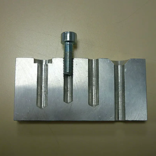
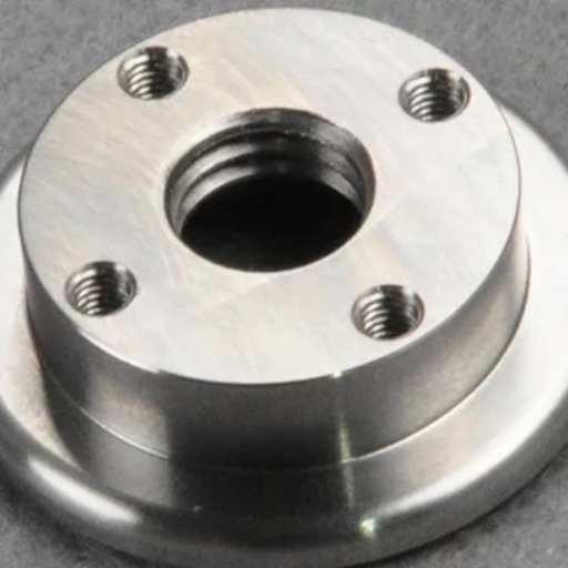
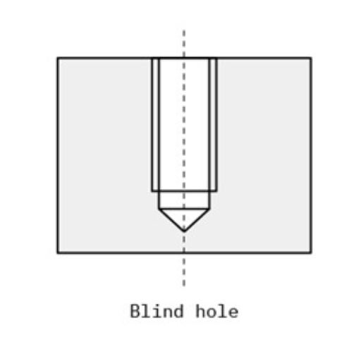
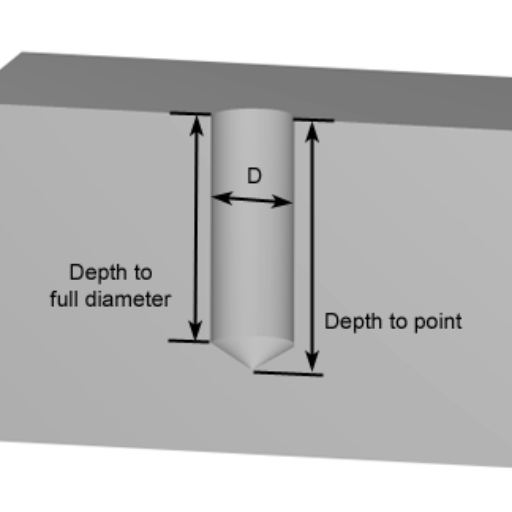
From a professional’s point of view, blind hole is a type of bore that does not perforate the entire material. Unlike through holes which go right across, blind holes have definite depths that cannot pierce the other side. Such holes are important in various engineering applications where it is necessary to maintain the integrity of outer surface of an element or when it is necessary to achieve exact depth for components like threads or fasteners. The ability to form accurate blind holes is evidence enough when talking about high level machining precision.
The Significance of Blind Holes in Engineering
As an industry expert I can confidently say that blind holes are very essential in engineering field. They allow for specific depths and internal configurations without affecting the external surface hence they are used for maintaining structural integrity of components. This characteristic becomes significant particularly in aerospace and automotive engineering where safety standards and performance requirements must be met by every component individually. Additionally, this allows for threading with tight fits that do not pass through the whole material and secure fittings and fastenings. This simply means that modern machining has advanced capabilities as evidenced by how precisely these holes are made enabling sophisticated designs and reliable end products.
Comparison between Blind Holes and Through Holes
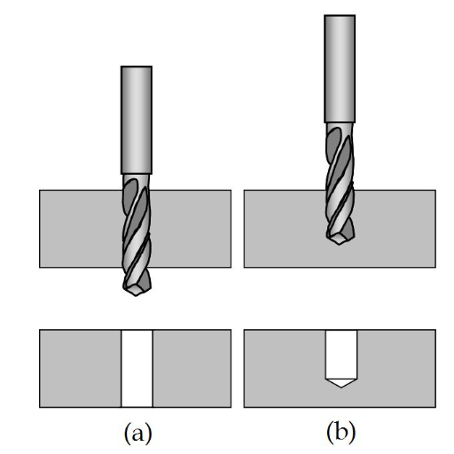
My perspective as an industry specialist convinces me that distinguishing between blind holes and through ones is cardinal and influential in machining operations. On one hand, there could be designed such blind holes whose extent will not exceed a certain limit even if they don’t go completely through materials employed while others might only work if thread connection without compromising on upper region has been made inside them so as to preserve outer surface of the component intact. Besides, this kind of feature is valuable in sectors such as aviation or motor-vehicle production where having smooth external aspects matters most for any given item being manufactured therefor e.g., “aerospace components.” In contrast however, a through hole refers to a hole that passes throw the entire material allowing for insertion of fasteners, bolts or other components which require full length penetration.
In practical terms, choosing between a blind hole and a through hole is often dependent on the requirements of the design and functionality of the part to be machined. For instance, through holes are advantageous because they make it easy to align objects and they facilitate long reach thus making them ideal in cases where there is need for secure attachment and uniform pressure. On the other hand, blind holes offer precision and control in more delicate or intricate configurations where it is important to maintain structural integrity on outer surfaces. Both types of these holes require detailed planning as well as execution thereby highlighting how advanced present-day machining processes have become.
How to Drill and Machine Blind Holes Effectively
The choice of the correct drill bit and drilling machine for blind holes
In drilling blind holes, it is important to choose a suitable drill bit and a drill press. Choosing the right drill bit and drill press is very important in order to achieve the desired outcome when drilling blind holes. According to my experience, high speed steel (HSS) and carbide tipped bits are very popular for drilling blind holes due to their strength as well as ability to withstand stresses associated with stopping short of full penetration. HSS bits can be used on various materials such as metals, plastics and wood because they are versatile and cost-effective. Conversely, carbide-tipped drills have better hardness and wear resistance which is essential when maintaining precision throughout extended use especially with harder materials.
Similarly important is selecting the best drill press. A variable speed drill press with depth control cannot be done without while doing blind hole drilling. The speed can be changed so that the tool works perfectly while minimising heat build-up or wearing out. Depth controls allow the user to accurately stop at certain points when making a blind hole, this way avoiding unintentionally making a through-hole. It is crucial that all these tools are properly calibrated before commencing work.
Checking the right depth using a depth indicator
One of the key actions that I have found necessary as an industry expert in achieving accurate blind holes involves using a depth indicator. Depth indicators will help you know how deep the drilling tool has gone down so that you don’t make mistakes into over-drilling through them by mistake. I usually calibrate my depth indicator before each project so that it matches exactly what I want from any hole being drilled onto them. In this way, rather than stopping repeatedly for measurement purposes or working blindly throughout, I can adjust things instantly without even having to check again in some instances since it provides me real-time progress tracking primarily when working with highly precise requiring materials; furthermore electronic ones over mechanical ones because they are easier to use and read. Even more so, the quality of drilled blind holes is greatly improved through an appropriate depth indicator set up and application which therefore leads to highly accurate machining in this field.
Techniques to Maintain the Quality and Precision of Blind Holes
Preserving blind hole quality and precision requires a mix of careful planning and state-of-the-art techniques. One strategy I depend on is using high-class drill bits that are made specifically for the material I work with. These bits stay sharper longer and produce cleaner cuts, which is crucial for maintaining the integrity of the hole. Furthermore, I always ensure that the drill bit lines up correctly with the job in order to avoid any deviation that could affect precision.
Another important technique is controlling speed and feed rate during drilling. By adjusting these two parameters in relation to material properties, I minimize heat generation and reduce chances of material deformation. For example, when working with softer materials, slower speed prevents melting or warping; while for hard materials, a constant feed rate helps prevent chipping or cracking.
Lubrication plays another critical role in preserving hole quality. To this end, I employ proper cutting fluids that minimize friction while dissipating heat thus making both drill bit’s life longer as well as ensuring smoother surfaces on the hole walls. Adequate lubrication becomes extra significant when it comes to metals since they are prone to severe defects from overheating.
Lastly, regular maintenance of both machines and tools cannot be overemphasized on enough occasions. Routine checks and adjustments by me make sure all my equipment remains at their best conditions possible at all times. This proactive approach minimizes unexpected issues during drilling and maintains high precision throughout the project implementation process. Consistent implementation of these techniques has enabled me achieve excellent quality blind holes meeting innovative machining requirements every time
Understanding the Callout Symbol of a Blind Hole in Technical Drawings
The power of interpreting the blind hole symbol in engineering diagrams
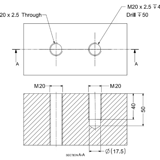
To interpret the blind hole symbol on engineering drawings is a necessary skill for anyone who is an expert in this field. In technical drawings, it can be represented by just a circle with some depth specified beside it. This means that the hole does not go through the entire work piece but rather stops at a certain depth. Additionally, I could state diameter and depth of the hole, thread specification if it’s tapped, whether a hole is counter sunk or counter bored and other references regarding this symbol. It ensures that parts manufactured are accurate enough as per design specifications thus avoiding costly mistakes and rework. In machine tool operations precision must be maintained; hence flawless symbols communication on blueprints is very vital.
The importance of clear callout symbols for machining accuracy
To underscore the significance of clear callout symbols in technical drawings, it is important to note that they ensure machining accuracy. These symbols act as a global language between designers and machinists through which accurate instructions of fabricating components are given. Let us investigate on what makes callout symbols important by looking at the parameters that are involved.
- Dimensional Specifications: among them is the diameter and depth of the blind hole. This eliminates chances of putting an oversized or under-sized hole that does not match with the design requirements.
- Thread specifications: If the blind hole is tapped for threading, it must be clearly identified in terms of thread type and size. As a result, this will allow its parts to amalgamate well with others from different parts when fitted together hence avoiding fitting challenges.
- Surface finish requirements: Surface finish designations are used by machinists to determine how smooth mating parts should be.
- Tolerance levels: The acceptable range within which to fit specified dimensions is indicated by tolerances. They help in achieving high precision since there are no errors resulting from clear tolerance symbols.
- Counterbore and Countersink Symbols: Another thing you may need to do after indicating these holes with geometries is adding counterbores or countersinks if necessary. Properly notated symbols prevent any confusion during machining.
- Material Specifications: Sometimes information about the material may also be added in such writing.T his would enable a machinist use right material that can affect drilling parameters and ultimately determine quality of finished products
By detailing all these parameters extensively on technical drawings, communication between design team and manufacturing teams becomes more efficient thus ensuring exactness between intended designs and produced parts.This accuracy is essential for both product quality as well as manufacturing efficiency and cost-effectiveness
Types of Holes in Engineering: Focus on Blind Holes
The variety of hole types used in engineering and machining
Some essential categories of holes used in engineering and machining are outlined by me as an industry expert, specially designed for specific purpose or application. Apart from non-through holes that do not go all the way through the workpiece, these are among the major types:
- Through Holes: These penetrate throughout the material in order to fix bolts, screws or any other type of fasteners solidly. They are commonly used when both sides of a material need to be joined together or when a passageway is required.
- Countersunk Holes: Made to ensure that the head of a bolt or screw is flat with or below the surface of the material; countersinking holes act as basic requirements where smooth uninterrupted surfaces must remain like in aerodynamics and aesthetics.
- Counterbored Holes: Counterbored are similar to countersunk holes but involve flattening out at their bottom; they contain socket-headed screws and other fasteners which require depression so as to keep outward surface flat.
- Tapped Holes: Screw or bolt can be directly inserted into these threaded holes. In cases where assembly may need frequent disassembly, tapped holes provide a secure reusable fastening solution.
- Pilot Holes: Drill smaller preliminary hole before using another larger drill bit for precise placement of holes and minimize chances of destroying materials during some subsequent drilling operations through misalignment.
- Spot-Faced Holes: This involves shallow recesses with flat bottoms around a hole in order to improve seating of bolts or other fasteners thereby improving structural integrity and appearance in an assembly.
Engineers and machinists can attain optimal performance, reliability, and efficiency in their designs and manufacturing processes by knowing how to use these different types of holes.
Key differences between blind holes and standard through holes
When it comes to design and manufacturing, understanding the main differences between blind holes and standard through holes is a must for an experienced industry player. Blind hole is drilled to a certain depth without piercing the material’s opposite side. This makes hidden fastening possible and is often used when one needs the back face of a part to stay as it was before or there are space limitations that prevent usage of through holes.
On the contrary, standard through holes go all the way through materials allowing such fasteners as bolts or screws to pass through them into components on both sides. It is vital for assemblies where maximum strength is required and accessibility from either side of the material.
While blind holes look neater and can be used in confined spaces, through holes allow easier assembly and are generally stronger. Thus, hole type selection depends upon project specifics requiring appropriate aesthetic versus functional trade-offs.
Where blind hole most commonly used
Blind holes are usually found in scenarios where aesthetics at the backside of a material matter or when there is no room for using thorough-holes. For instance, in furniture assembly visible bolts can ruin the overall appearance while in automotive assembly where parts might be tightly packed hence necessitating secure fastenings that do not damage outer surfaces. Furthermore, blind holes have caught up with electronics whereby internal components need rigid mounting without tampering with external casings. The resultant structure maintains stability but also presents a neat professional design.
Applications of Blind Holes in Various Industries
Case studies: The application of blind holes in the aerospace and automotive industries
Through my involvement in the aerospace industry, it became apparent to me that blind holes are essential for preserving both the structural soundness and aerodynamic proficiency of planes. Parts of planes must be joined together with great care often requiring secure fastenings without compromising the sleek smoothness of the outer surfaces. For example, blind holes allow for installation of rivets and fasteners on one side during airframe construction, hence creating a low-drag aerodynamic profile. In this way both performance is heightened while maintaining aesthetic precision required by aerospace engineers.
Now let us focus our attention on the car manufacturing sector where blind-holes play an equally vital role especially when dealing with space constrained applications. In modern vehicles’ design and manufacturing processes components like engine blocks, transmission housings, interior paneling among others often include blind-holes. This means that there can be attachment points without having to drill completely through material which may compromise its strength or sacrifice its beauty inside cars. As a result, I have experienced that when they are employed in critical engine parts like those mentioned above blind holes allow for fastening devices into tight spaces thus keeping external appearance clean while providing strong mechanical connections necessary for smooth functioning of an automobile.
Consequently, based on these case studies it is evident that strategic implementation of such elements as blind holes within both automobile and airplane sectors not only addresses their functional implications but also keeps pace with technical and visual requirements imposed by these challenging production settings.
Why are Blind Holes so Important to Electronic Component Manufacturing?
As a specialist in this field, I can confirm that making use of blind holes in electronic component manufacturing is highly important in order to enhance their functionality. Precise designing of electronic equipment requires accuracy and better use of space leading to adoption of this feature as explained below. A typical example is printed circuit boards (PCBs) where components could be attached using conventional through holes but such an approach would have made the gadget to be bigger and heavy. Instead, it is my understanding that applying blind holes in printed circuit board (PCB) design allows us to maintain its small size besides holding together different electronic components. This method also helps in cooling down by maintaining a temperature range which is needed for life time and effectiveness of most electronics. It is worth mentioning that this kind of drills make it easy during assembly and service thus allowing engineers to build more advanced electronics that are highly reliable at the same time very compact as required by today’s world full of future technologies.
Expert Tips for Drilling Perfect Blind Holes
Best practices for starting a blind hole: pilot hole and core hole strategies.
While starting a blind hole, I go with making the pilot hole as my main strategy. It is important to understand that this initial step not only acts as a guide during the drilling process but also prevents the drill bit from wandering. Pilot holes are normally much smaller in diameter than the final hole thereby allowing more accuracy and control over it. Through a proper selection of pilot-hole size depending on material and application, I make sure that the finished blind holes are accurate and clean.
After pilot drilling, I usually move on to drilling the core hole. The core hole should have similar diameter with its corresponding blind hole and hence it is necessary to use high-quality drill bits so as to obtain a good finish. In my experience, incremental drilling techniques whereby the size of the drilled material increases gradually can prevent material stress thereby enhancing overall quality of drilled holes. Additionally, lubrication must be done carefully during this step to minimize heat build-up and wear on the bit.
Combining these approaches also helps improve precision in creating blind holes while increasing efficiency and durability of end products thus making this procedure reliable both in manufacturing electronic components and other sectors.
Finishing tactics: Using a bottom tap to thread blind holes
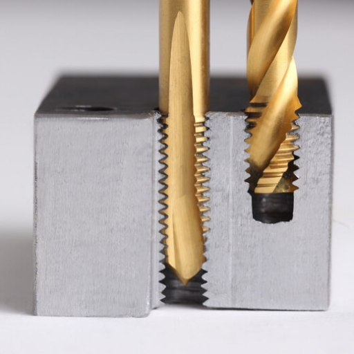
As an industry expert, I cannot emphasize enough about using bottom taps when threading blind holes. Furthermore, plug tap or bottom tap helps in cutting threads at nearly lowest part of any closed ended channel hence maximizing thread engagement.Ensure that there is no waste inside your tap by flushing compressed air or appropriate cleaning solution through it before commencing tapping process. This stage plays such vital role since remaining remnants might impede threading process or harm tap itself severely.
In tapping into the borehole, apply constant pressure then use high-quality lubricant for smooth cutting out sections. These processes should be slow as well so that chips are cleared away from time to time by reversing taps therefore preventing clogging and cleaning the thread. Attention to the depth of the tapping operation ensures that threads reach required specification without compromising material integrity.
By following these procedures closely, you will be making high-quality threads as well as extending the life of both the tap and component being worked on. Precise threading of blind holes underpins accurate and dependable electronic component manufacturing among other precision-driven sectors.
Avoiding common drilling errors with blind holes
Precision and integrity are ensured by avoiding common drilling mistakes when working with blind holes, one of which is using the wrong drill bit that results in an incorrect hole size and inadequate depth. One must always select a drill bit meant for fashioning your blind holes while considering its material specification. Another error is failing to secure the workpiece properly, leading to instability and misalignment. Clamping the workpiece securely will prevent movement and ensure accurate drilling.
Moreover, failure to control feed rate results in overheating as well as tool wear. To avoid these problems, keep a consistent feed rate that is appropriate. Furthermore, many people often forget to use cutting fluid or lubricant thereby increasing friction and reducing hole quality. Applying lubricant ensures cleaner cuts and extends tool life.
Lastly, this can block up the hole as well as damage the drill bit if chips are not removed properly. Occasionally retract the drill for chip removals for smooth operation consistency. By following these instructions you will achieve error-free, precise and dependable outcomes whenever you have to do any blind hole drilling tasks.
Reference sources
1. Online Article: “Understanding Blind Holes in Machining: Techniques and Applications” – Modern Machine Shop
- Source: Modern Machine Shop
- Summary/Annotation: This article from Modern Machine Shop offers an in-depth overview of blind holes in machining, discussing the techniques used to create them, the tools involved, and their various applications in different industries. It covers key aspects such as drilling parameters, tooling considerations, and strategies to ensure precision and avoid common pitfalls like incomplete holes or damage to the workpiece. The article also highlights real-world examples and case studies where blind holes are critical. Modern Machine Shop is a well-regarded publication in the manufacturing industry, ensuring the content is accurate and practical. This source is valuable for readers seeking a clear and thorough understanding of how to effectively create and utilize blind holes in machining.
2. Academic Journal: “Optimization of Drilling Parameters for Blind Holes: A Study on Surface Finish and Dimensional Accuracy” – Journal of Manufacturing Processes
- Source: Journal of Manufacturing Processes
- Summary/Annotation: This peer-reviewed paper published in the Journal of Manufacturing Processes examines the optimization of drilling parameters for creating blind holes, focusing on achieving superior surface finish and dimensional accuracy. The study includes experimental data on the effects of various parameters such as cutting speed, feed rate, and tool geometry. It provides insights into how these factors can be adjusted to minimize defects and enhance the quality of blind holes. As an academic journal, this source offers high credibility and technical depth, making it essential for readers interested in a rigorous scientific understanding of the best practices for optimizing the creation of blind holes in machining processes.
3. Manufacturer Website: “Blind Hole Drilling: Techniques, Tools, and Best Practices” – Kennametal
- Source: Kennametal
- Summary/Annotation: Kennametal’s website provides detailed information about blind hole drilling, including the techniques, tools, and best practices for achieving precision and efficiency. The site features technical datasheets, application notes, and guidelines for selecting the appropriate drills and cutting conditions for different materials and hole depths. It also offers practical tips for troubleshooting common issues and improving the performance of blind hole drilling operations. Kennametal is a leading manufacturer of cutting tools and machining solutions, ensuring authoritative and practical insights. This source is crucial for professionals seeking reliable information on the capabilities and applications of blind hole drilling in various engineering contexts.
Frequently Asked Questions (FAQs)
Q: What is a blind hole in machining?
A: A blind hole is a hole that was drilled through a material, but it doesn’t go all the way through. It stops at some depth unlike through holes. Blind holes are used for several applications including being the site for threaded fasteners in machining and engineering.
Q: How do you drill blind holes accurately?
A: Drilling blind holes requires precision of depth accuracy without breaking through the material. For accurate drilling of such holes use a drill press to stabilize your drill, set your depth stop correctly, start with a pilot hole to follow and occasionally pull out the drill bit to remove chips from within its mouth. CNC machining can help maintain accuracy and prevent tool breakage by programming the correct depth and using peck drilling cycle.
Q: What are the different types of holes in machining?
A: In machining, there are several kinds of holes like blind holes which are also called tapped holes (threaded), countersink holes which allow fasteners to sit flush with material surface, tapered bores meant for specific purposes etcetera Each type of hole has different uses and requires distinct tools as well as techniques during its fabrication.
Q: How does blind hole machining differ from drilling through holes?
A: The key difference between blind hole machining and drilling through-holes lies in that a blind hole is drilled into the work material up to certain specified depths until it fails to pass through while a through-hole goes completely via thwork material. This difference affects choice of tools, methods such as marking required depths by putting tape or using stop collars or stops such as piece of wood covering top part of drill so that only required length bits will be exposed during drilling process itself plus getting rid off chips from its mouth after boring operation has been completed.
Q: What are some commonly used fasteners for blind holes?
A: Blind holes can be threaded by such kinds of fasteners as screws and bolts that do not need to go through the entire material. The thread in the blind hole may be in the form of tapped hole or directly into the material itself whereupon a fastening item is engaged with it. They are used in assemblies which require a neat look on one side or where damage to or weakening of the material might arise from through penetration.
Q: Can you drill blind holes using CNC machining?
A: Yes, CNC machining is very good at drilling precise blind holes. Using CNC machines, operators can set their required hole dimensions including its position on a workpiece, diameter and depth. In this regard, the same kind of hole is replicated across different parts. CNC drilling also facilitates better accuracy when dealing with more complicated hole profiles like those that have tapers and others that are perpendicular.
Q: What are some challenges faced while drilling blind holes and how to overcome them?
A: A challenge that comes with drilling a blind hole concerns keeping correct depth, avoiding chips inside before re-cutting heat up again then making sure that drill bit does not move while starting off hole thereby making it difficult to find proper location. This can be mitigated by increasing stability through use of either drill press or CMC machine; beginning the process of puncturing an accurate aperture with any pilot-or-center-drill; maintaining constant cooling and lubrication by utilizing appropriate cutting fluids besides getting rid of chips often times. Moreover, specific chip-evacuation features should be anticipated after going for bits created explicitly for covering up dislodging points.
Q: How important is it to have accurate hole depths for blind hole machining?
A: Hole depth is essential during machining since it defines how far into the material a fastener or other component can go into it. Furthermore, it affects joint/assembly strength and integrity. With the correct hole depth, there is no danger of a threaded hole’s fastener bottoming out or slipping off as the grip will be enough to hold it properly. This holds particular importance in applications exposed to high stress levels.


